Contactless power supplying system and metal foreign object detection device of contactless power supplying system
a technology of contactless power supply system and detection device, which is applied in the direction of batteries, inductance, instrumentation, etc., can solve the problems of limited detection of sandwiched metal foreign objects, small signal attenuation, and inability to detect metal foreign objects, etc., to achieve low cost, simple structure, and high sensitivity
- Summary
- Abstract
- Description
- Claims
- Application Information
AI Technical Summary
Benefits of technology
Problems solved by technology
Method used
Image
Examples
second embodiment
[0166]A second embodiment will now be described with reference to FIGS. 12, 13 and 14.
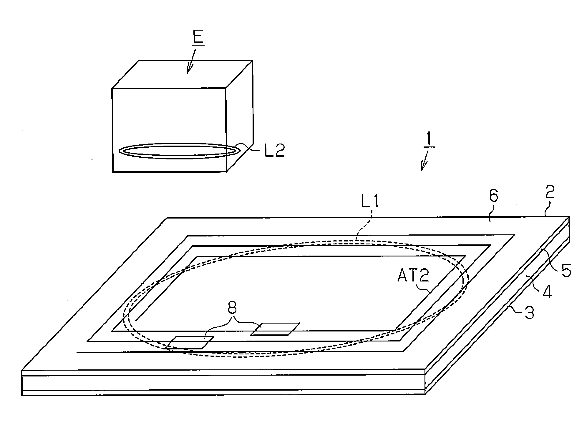
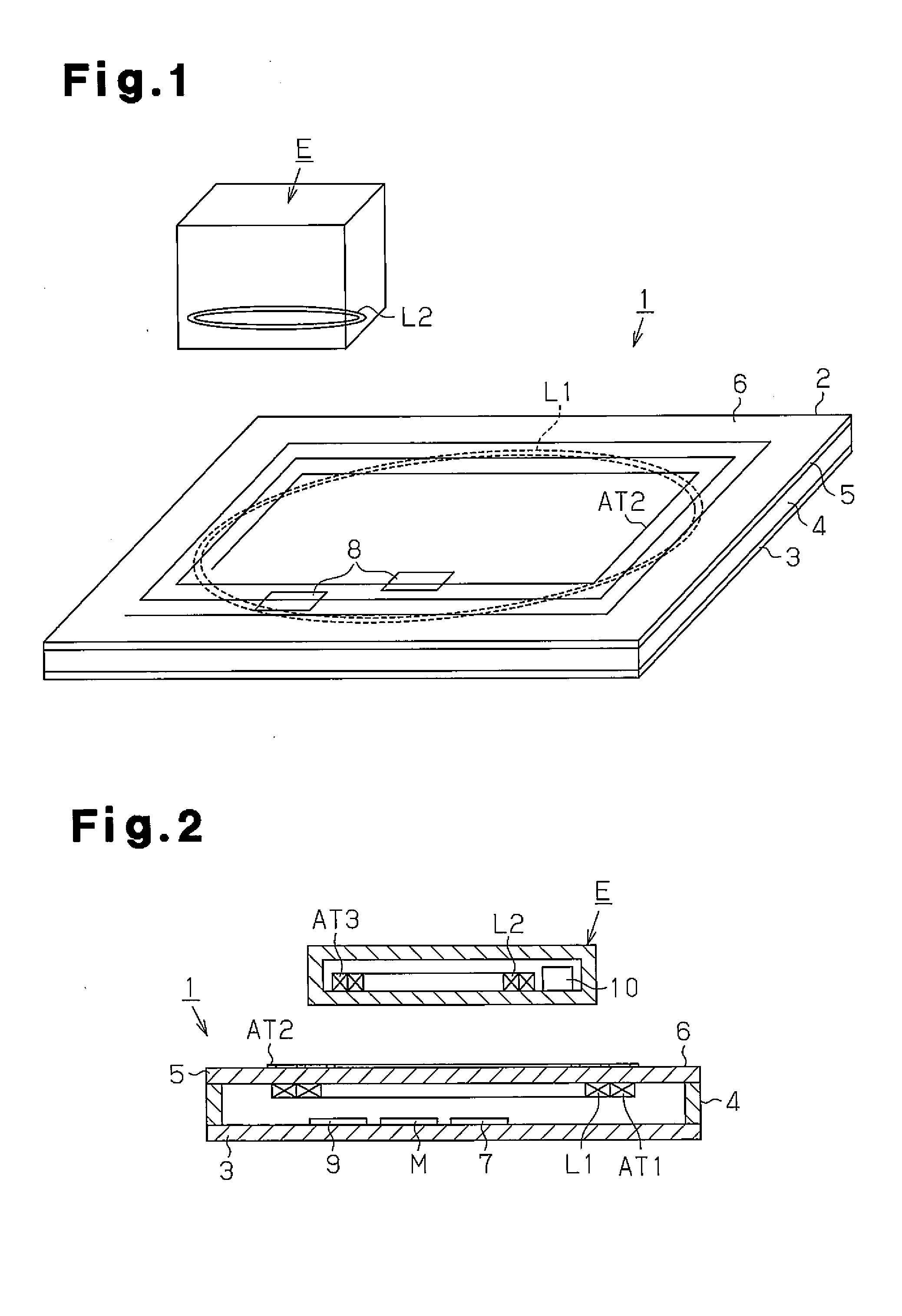
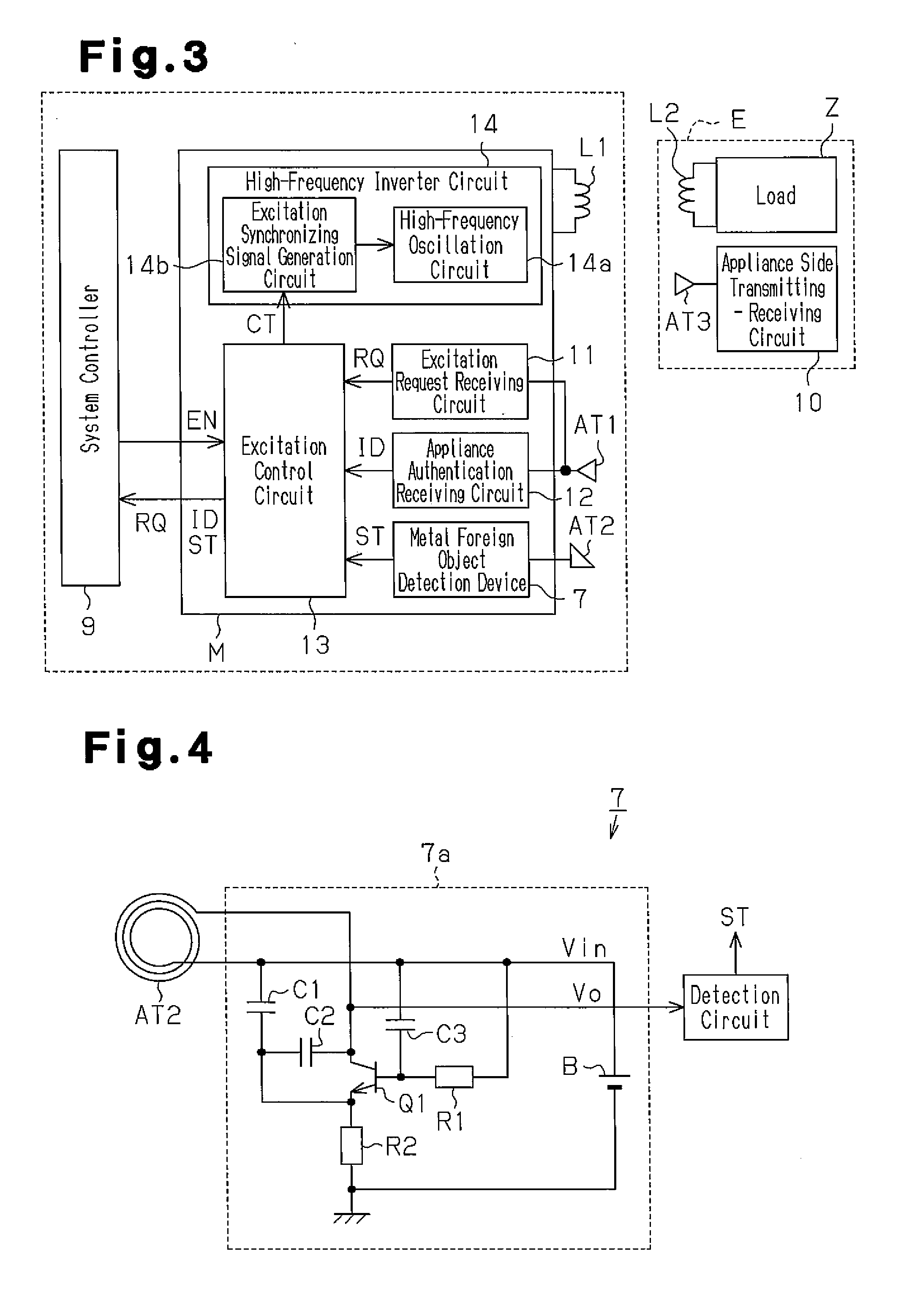
[0167]In the power supplying device 1 of the first embodiment, the power supplying device 1 includes the single metal detection antenna coil AT2. The feature of this embodiment is in that the power supplying device 1 includes a plurality of metal detection antenna coils AT2.
[0168]For the sake of the brevity, same reference numerals are given to those components that are the same as the corresponding components of the first embodiment. Such components will not be described in detail.
[0169]In FIG. 12, a plurality of (twenty in FIG. 12) metal detection antenna coils AT2 are formed on the setting surface 6 of the power supplying device 1. The metal detection antenna coils AT2 of this embodiment have a size that is one twentieth of the metal detection antenna coil AT2 of the first embodiment. Five are arranged in the X direction and four are arranged in the Y direction on the setting surface 6. Each met...
third embodiment
[0183]A third embodiment will now be described with reference to FIGS. 16 and 17.
[0184]In the first and second embodiments, the metal foreign object detection device 7 is arranged in the power supplying device 1. In this embodiment, the metal foreign object detection device 7 is arranged in the appliance E.
[0185]For the sake of brevity, same reference numerals are given to those components that are the same as the corresponding components of the first embodiment. Such components will not be described in detail.
[0186]In FIG. 16, a plurality of (four in this embodiment) metal detection antenna coils AT2 are formed on a lower surface of the housing of the appliance E, that is, a power receiving surface that comes into contact with the setting surface 6 of the power supplying device 1. In the same manner as the first and second embodiments, each metal detecting antenna coil AT2 is formed to have a spiral shape on the lower surface by a known printed wiring method. In this embodiment, a ...
fourth embodiment
[0202]A fourth embodiment will now be described with reference to FIGS. 18, 19, 20, and 21.
[0203]In the first and second embodiments, the metal foreign object detection device 7 is arranged in the power supplying device 1. In the third embodiment, the metal foreign object detection device 7 is arranged in the appliance E. The feature of this embodiment is in that the metal foreign object detection device 7 is arranged in a distributed manner in the power supplying device 1 and the appliance E.
[0204]For the sake of brevity, same reference numerals are given to those components that are the same as the corresponding components of the first embodiment. Such components will not be described in detail.
[0205]As shown in FIG. 18, a plurality of (four in this embodiment) metal detection antenna coils AT2 are formed in the lower surface of the housing of the appliance E, that is, the power receiving surface that comes into contact with the setting surface 6 of the power supplying device 1. I...
PUM
| Property | Measurement | Unit |
|---|---|---|
| frequency | aaaaa | aaaaa |
| magnetic field | aaaaa | aaaaa |
| voltage | aaaaa | aaaaa |
Abstract
Description
Claims
Application Information
 - R&D
- Intellectual Property
- Life Sciences
- Materials
- Tech Scout
- Unparalleled Data Quality
- Higher Quality Content
- 60% Fewer Hallucinations
Browse by: Latest US Patents, China's latest patents, Technical Efficacy Thesaurus, Application Domain, Technology Topic, Popular Technical Reports.
© 2025 PatSnap. All rights reserved.Legal|Privacy policy|Modern Slavery Act Transparency Statement|Sitemap|About US| Contact US: help@patsnap.com


