High-voltage sensor with axially overlapping electrodes

a high-voltage sensor and electrode technology, applied in the field of voltage sensors, can solve the problems of limited attractiveness of optical sensors, large size of high-voltage insulators, and common interference of light waves at polarizers

Active Publication Date: 2013-04-25
HITACHI ENERGY LTD
View PDF4 Cites 8 Cited by
  • Summary
  • Abstract
  • Description
  • Claims
  • Application Information

AI Technical Summary

Benefits of technology

[0032]The present disclosure in its exemplary embodiments provides a high-voltage sensor with a slender and light-weight insulator of low cost. The electrodes provide electric field steering and, optionally, obviate the need for electrodes directly applied to the field sensor. A solid-state insulation may suffice (no oil or gas).
[0033]The present disclosure also relates to an assembly of such high-voltage sensors in series. Hence, a combination of several modules of the same or differently shaped or dimensioned high-voltage sensor can be used for measuring a large range of different voltage levels.
[0034]Other exemplary embodiments are listed in the dependent claims as well as in the description below.

Problems solved by technology

At the end of the crystal, the light waves commonly interfere at a polarizer.
A drawback of the above concepts is the requirement of an expensive high-voltage insulator of large size.
Thus, the attractiveness of such optical sensors is limited.
A drawback is that relatively large corona rings are required in order to ensure that the voltage drops at the individual crystals are of comparable magnitude.

Method used


Image

  • High-voltage sensor with axially overlapping electrodes
  • High-voltage sensor with axially overlapping electrodes
  • High-voltage sensor with axially overlapping electrodes

Examples


Embodiment Construction

[0025]Exemplary embodiments of the present provide a voltage sensor for measuring a voltage between a first contact point and a second contact point of alternative design.

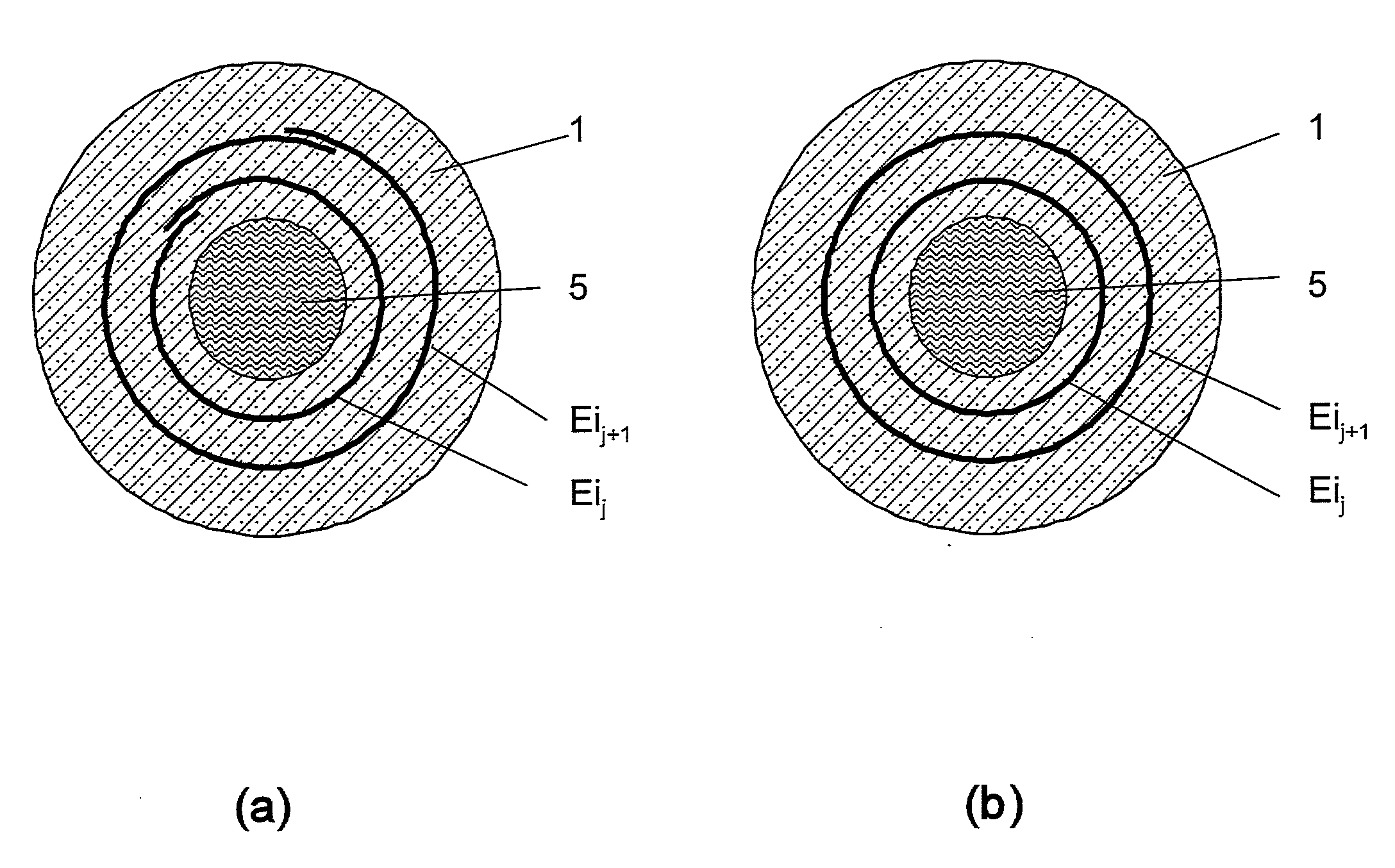
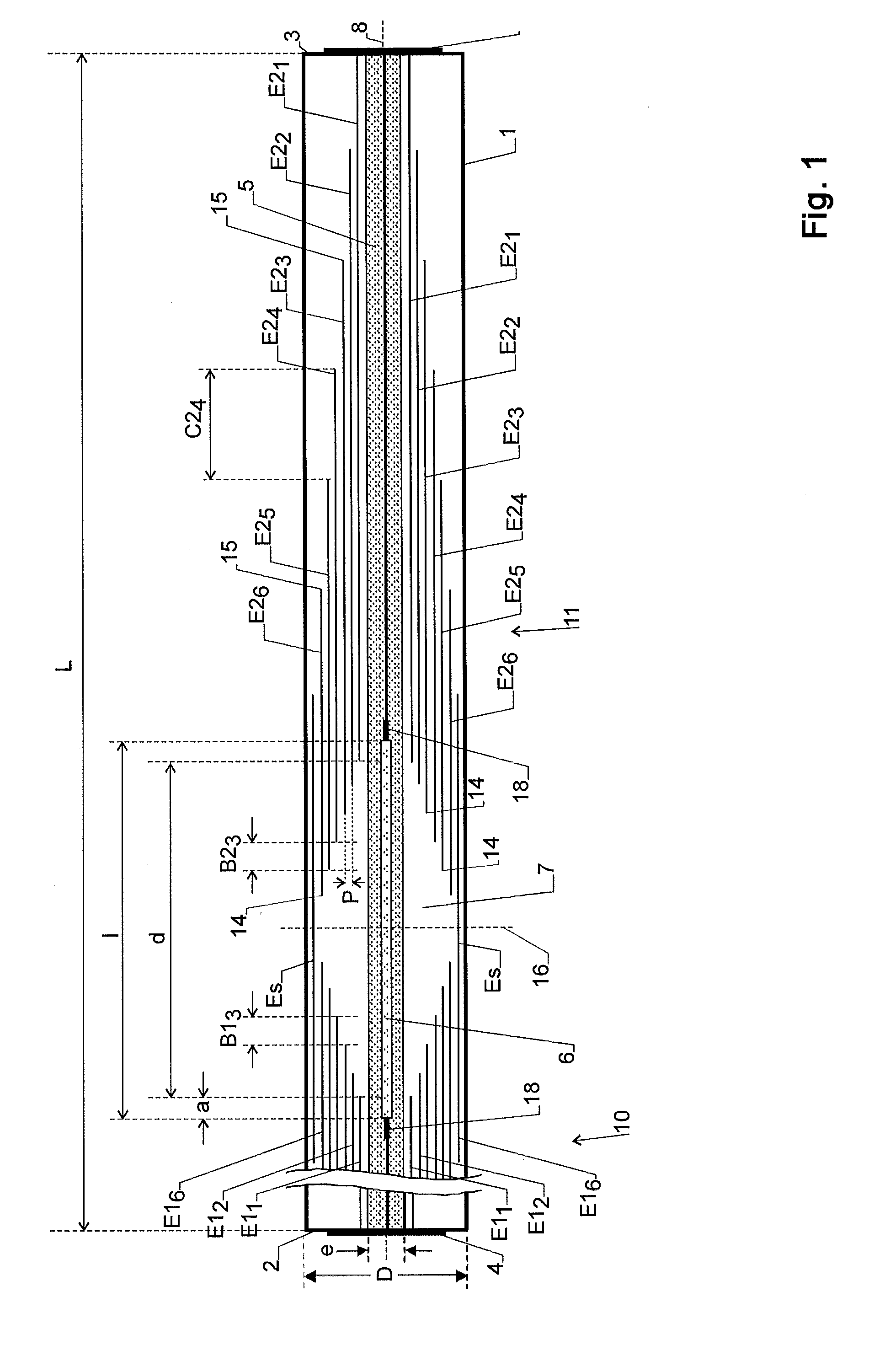
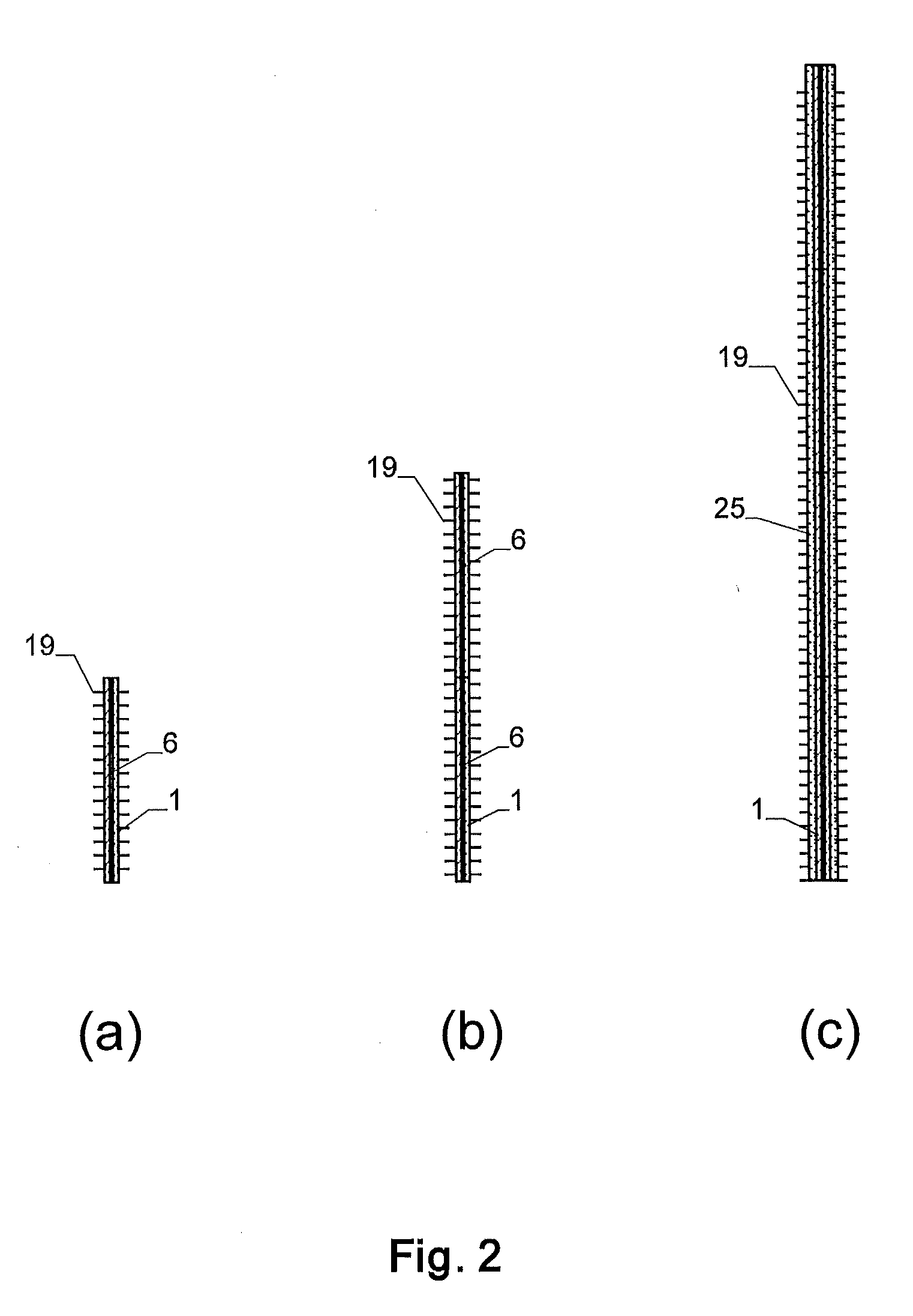
[0026]An exemplary embodiment of the present disclosure provides a high-voltage sensor for measuring a voltage between a first contact point and a second contact point. The high-voltage sensor includes an insulator, or briefly, a sensor insulator. The insulator is elongate and extends along an axial direction between the first and second contact points. An electric field sensor is arranged within at least one sensing cavity, for example, within exactly one sensing cavity, inside the insulator. In accordance with an exemplary embodiment, the length of the sensing cavity is significantly shorter than the length of the insulator. Further, a plurality of conductive electrodes is arranged in the insulator. The electrodes are mutually separated by the insulating material and capacitively coupled to each other. At least a...


PUM


Abstract

A voltage sensor includes an insulator with mutually insulated electrodes embedded therein. The electrodes are coaxial and cylindrical and overlap axially along part of their lengths. They are mutually staggered and control the surfaces of electric equipotential such that there is a substantially homogeneous electric field outside the insulator and a substantially homogeneous but higher field within a sensing cavity within the insulator. A field sensor is arranged within the sensing cavity to measure the field. This design allows for the production of compact voltage sensors for high voltage applications.

Description

RELATED APPLICATION(S)[0001]This application claims priority as a continuation application under 35 U.S.C. §120 to PCT / EP2011 / 059399, which was filed as an International Application on Jun. 7, 2011, designating the U.S., and which claims priority to International Application PCT / EP2010 / 057872 filed on Jun. 7, 2010. The entire contents of these applications are hereby incorporated by reference in their entireties.FIELD[0002]The present disclosure relates to a voltage sensor for measuring a voltage between a first and a second contact point. More particularly, the present disclosure relates to a voltage sensor with an insulator, such as a body of an insulating material, extending between the contact points and with electrodes arranged in the body. The present disclosure also relates to an assembly of several such voltage sensors arranged in series.BACKGROUND INFORMATION[0003]In the following description, publications referenced herein are identified with bracketed numbers (e.g., [1]) ...

Claims


Application Information

Patent Timeline
Patent Type & Authority Applications(United States)
IPC IPC(8): G01R19/00
CPCG01R19/0046G01R15/242G01R1/06G01R15/14G01R15/18G01R19/00
Inventor WILDERMUTH, STEPHANBOHNERT, KLAUSKOCH, NORBERTCZYZEWSKI, JANMARCHESE, SERGIO VINCENZO
Owner HITACHI ENERGY LTD
Why Eureka
Try Eureka