Blind Spot Detection System and Blind Spot Detection Method Thereof

a blind spot detection and detection system technology, applied in closed circuit television systems, television systems, instruments, etc., can solve problems such as accidents, driver and other people involved may be injured, and achieve the effects of enhancing image recognition percentage, reducing detection errors, and enhancing driving safety

Inactive Publication Date: 2013-04-25
ALTEK AUTOTRONICS
View PDF1 Cites 24 Cited by
  • Summary
  • Abstract
  • Description
  • Claims
  • Application Information

AI Technical Summary

Benefits of technology

[0015](1) The blind spot detection system and method keep operating for a period of time after the car is moving at a speed less than 10 Km/h, or situated at a car stopping state, or even after the driver switches off the ignition switch of the car. The blind spot detection system and method will stop operating, until the driver gets off the car, closes the car door, and starts an anti-burglar device. Therefore, the invention not only detects the blind spots around the car to enhance the driving safety

Problems solved by technology

In a crowded environment filled with many cars, accidents may occur even if the car remains still.
For example, an accident may occur when the car i

Method used


Image

  • Blind Spot Detection System and Blind Spot Detection Method Thereof
  • Blind Spot Detection System and Blind Spot Detection Method Thereof
  • Blind Spot Detection System and Blind Spot Detection Method Thereof

Examples


Embodiment Construction

[0023]The technical characteristics of the present invention will become apparent with the detailed description of the preferred embodiments accompanied with the illustration of related drawings as follows. It is noteworthy to point out that same numerals are used for representing respective elements in the description of the following preferred embodiments.

[0024]The blind spot detection system and the blind spot detection method of the present invention are applicable to a transportation vehicle such as a car, a motorcycle, a bicycle or any transportation means used for carrying passengers or goods, but the scope of applicability is not limited to the aforementioned transportation vehicles only.

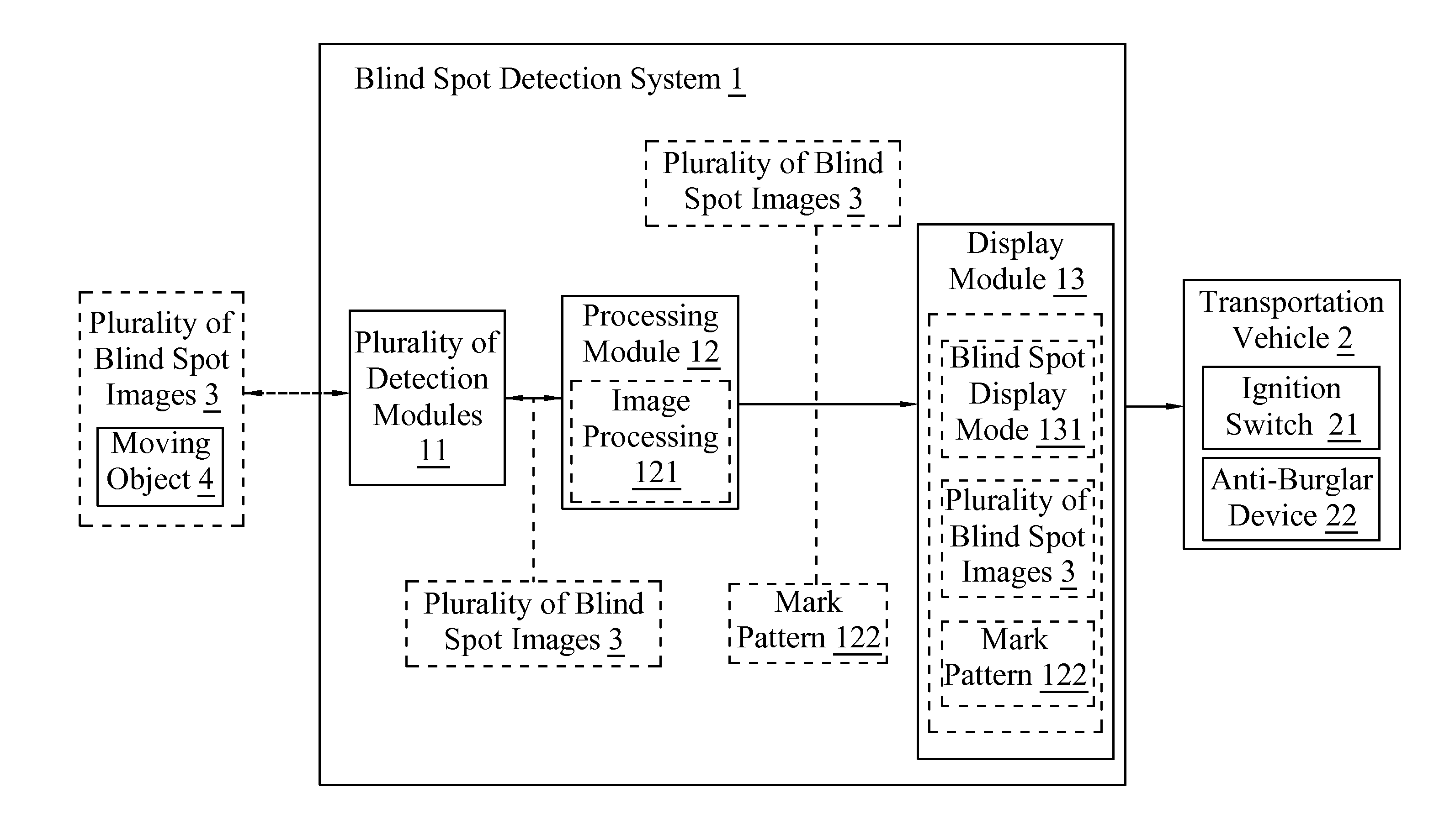
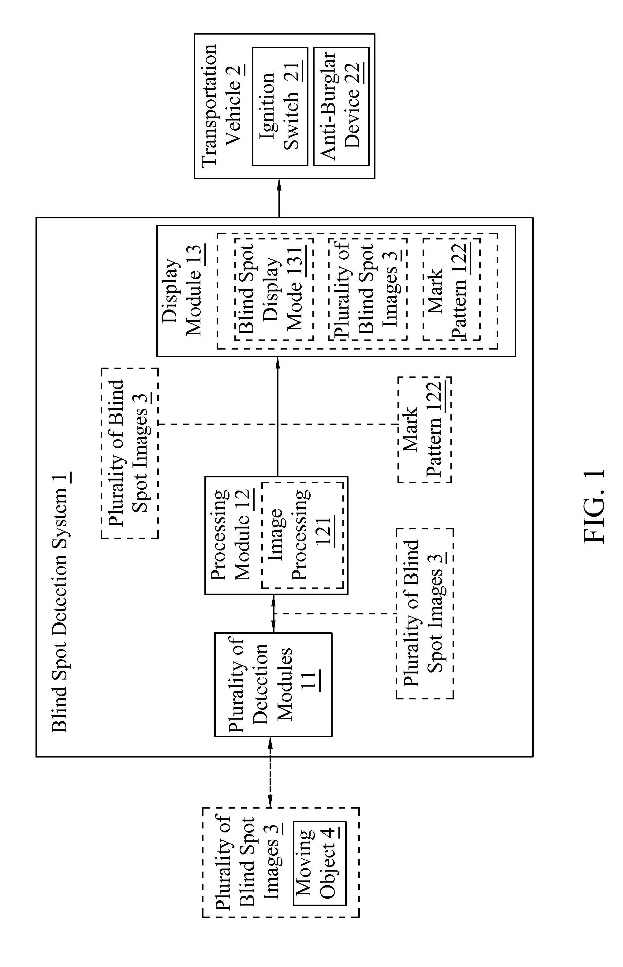
[0025]With reference to FIG. 1 for a schematic view of a blind spot detection system in accordance with the first preferred embodiment of the present invention, the blind spot detection system 1 can be disposed on a device of a transportation vehicle 2, wherein the transportation vehicle 2 c...


PUM


Abstract

A blind spot detection system and method thereof applicable to a transportation vehicle. The blind spot detection system comprises a plurality of detection modules, a processing module and a display module. When the transportation vehicle moves at a speed less than a predetermined speed or at a stop moving state, each detection module is used to detect a plurality of blind spot images around the transportation vehicle. The processing module is connected to each detection module and used to receive the plurality of blind spot images and execute an image processing for detecting and identifying a moving object in the plurality of blind spot images, and to generate a mark pattern corresponding to the moving object. The display module is connected to the processing module and used to display the plurality of blind spot images and the mark pattern in a blind spot display mode.

Description

CROSS-REFERENCE TO RELATED APPLICATION[0001]This application claims the benefit of priority to Taiwan Patent Application No. 100138571, filed on Oct. 25, 2011, in the Taiwan Intellectual Property Office, the disclosure of which is incorporated herein in its entirety by reference.FIELD OF THE INVENTION[0002]The present invention relates to a blind spot detection system and a blind spot detection method thereof, in particular to the blind spot detection system and method for detecting a blind spot when a car is moving at a speed less than 10 Km / h, or situated at a stopping state, or even when an ignition switch of the car is switched off.BACKGROUND OF THE INVENTION[0003]Most blind spot detection (BSD) systems are disposed on both left and right sides of a car, such as both ends of a rear view mirror or both sides of a bumper at the rear of the car. The BSD system is mainly used for detecting the distance and speed of a moving object at a left or right blind spot of the car, and furthe...

Claims


Application Information

Patent Timeline
IPC IPC(8): H04N7/18
CPCG08G1/167
Inventor CHIEN, CHUN-LIANGTU, CHIH-CHENGTSAI, CHIH-WOEI
Owner ALTEK AUTOTRONICS
Why Eureka
Try Eureka