
Device for splitting light into components having different wavelength ranges and methods of use

a technology of light splitting and components, applied in the field of optics, can solve the problems of high component cost, complicated separation and detection of multi-color fluorescent wavelengths from total emission spectra due to multiple fluorescent labels, and achieve the effect of maximizing receipt or entry

Active Publication Date: 2013-04-25
AGILENT TECH INC
View PDF4 Cites 28 Cited by
  • Summary
  • Abstract
  • Description
  • Claims
  • Application Information

AI Technical Summary

Benefits of technology

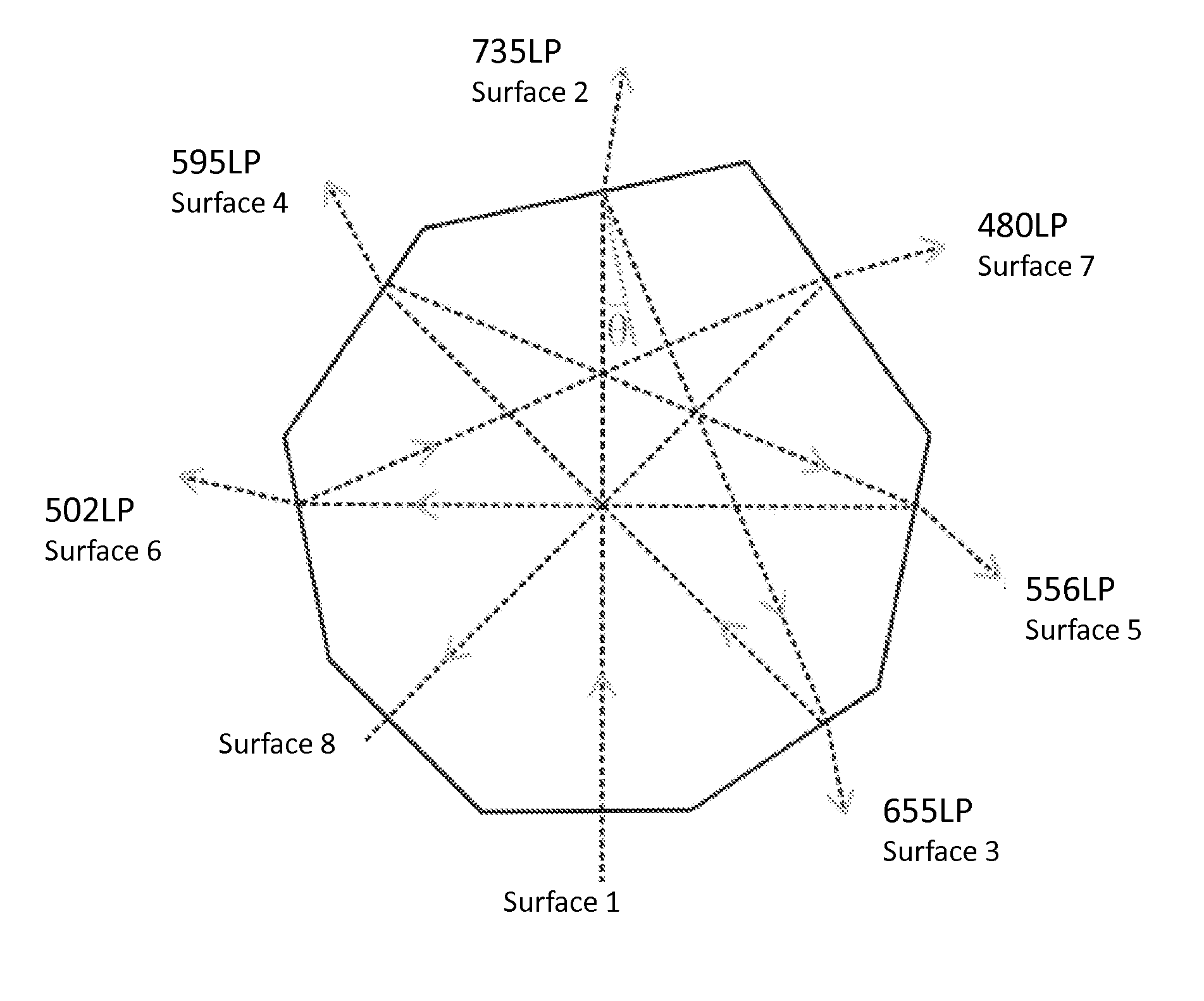
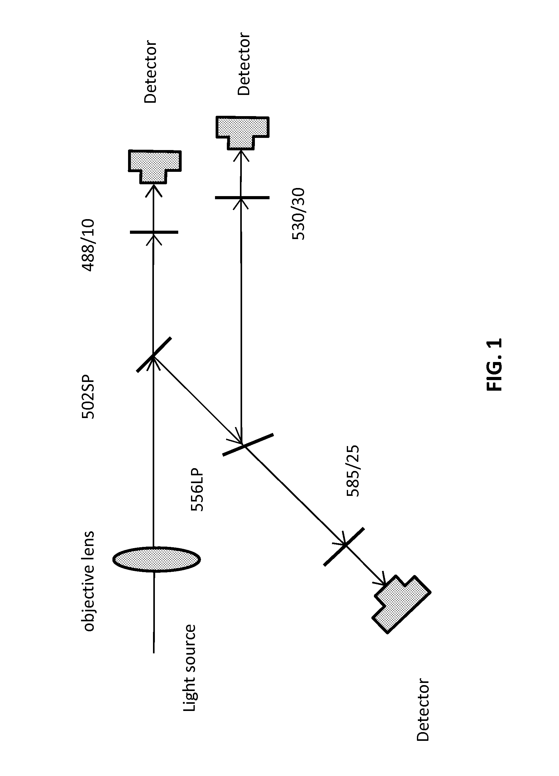
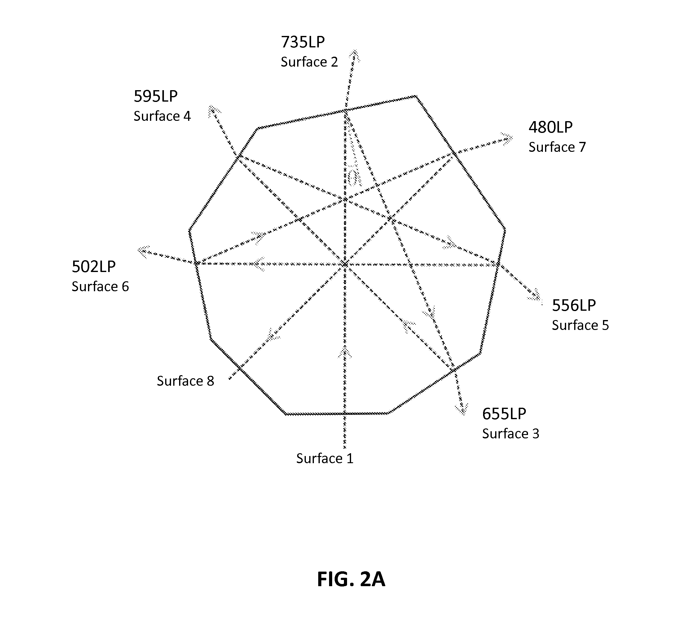
The patent describes a device called a prism that can receive an optical signal, like a light spectrum or a sample emission spectrum, through its entry surface. The entry surface is coated with a special coating to maximize the amount of light that enters the prism. The prism has multiple surfaces that can direct the light towards specific filters, which then separate the light into its various narrower wavelengths. This allows for precise measurement and analysis of the light spectrum.

Problems solved by technology

Separation and detection of these multi-color fluorescent wavelengths from the total emission spectra due to the multiple fluorescent labels is further complicated by additional measurements of forward scatter (FSC) and even more problematic, side scatter (SSC), which also require detection after exposure to the laser beam(s).
These approaches, whilst being adopted in many types of optical instruments, such as flow cytometers or some fluorescent microscopes, suffer from a number of limitations or shortcomings due to the use of a large number of optical components, such as: (1) high component cost; (2) lengthy and complicated optical alignment processes to achieve proper and efficient light splitting; and (3) large space requirements to cope with multiple components as well as their holders and to avoid spatial / mechanical interference between these components.
Thus, there remains a need to develop new optical light-splitting technologies which have simplified optical alignment procedures, occupy a small space and result in a lower cost.

Method used


Image

  • Device for splitting light into components having different wavelength ranges and methods of use
  • Device for splitting light into components having different wavelength ranges and methods of use
  • Device for splitting light into components having different wavelength ranges and methods of use

Examples


example 1

[0085]N-BK7 glass was shaped to form an eight-faced prism, a 3-dimensional representation of which is shown in FIG. 5A. The eight surfaces were shaped to the same geometrical dimensions as that shown in FIG. 2B. This prism was produced to show the light-splitting functionality of light-splitting prism of the present invention. To simplify the production process and to demonstrate the operational principle of the light-splitting prism, three surfaces were coated with optical coatings having short-pass or band-pass properties. The design requirements for Surface 2, 5 and 6 are provided in TABLE 1:

TABLE 1SurfaceNumberTransmission >90%Transmission = 50%Reflection >98%Surface #5480-495 nm503-513 nm514-820 nmSurface #2500-550 nm550-560 nm565-820 nmSurface #6550-620 nm635-645 nm660-820 nm

[0086]FIGS. 5B and 5C show the transmission and reflection spectra, respectively, for Surface #2 and Surface #5 of the prism produced based on the design requirement in above table. Transmission of 50% occ...


PUM


Abstract

A prism including a substrate faceted to provide a plurality of flat surfaces, wherein at least two of the plurality of surfaces, each including a filter coating, form at least two filter surfaces, wherein each filter surface selectively permits passage of a predetermined wavelength and reflects remaining wavelengths along an optical path towards another of the plurality of surfaces, optionally another filter surface, wherein an angle of incidence of each of the plurality of surfaces along the optical path is equal or nearly equal. An apparatus incorporating the prism and its use for splitting a light spectrum into a plurality of wavelengths or wavelength ranges.

Description

CROSS REFERENCE TO RELATED APPLICATIONS[0001]This application claims benefit of priority to U.S. provisional patent application Ser. No. 61 / 549,379, filed Oct. 20, 2011; the contents of which are herein incorporated by reference in their entirety.TECHNICAL FIELD[0002]The present invention relates generally to the field of optics and more specifically to a prism, an apparatus incorporating the prism and its use for splitting a light spectrum into a plurality of wavelengths or wavelength ranges by selectively delivering the light spectrum across a series of filtering surfaces of the prism. Uses for the prism and apparatus include systems and methods for flow cytometry, multiple fluorescent color detection methods, fluorescent microscopy, and optical detection systems and methods requiring splitting of light into components having different wavelength ranges.BACKGROUND OF THE INVENTION[0003]A number of optical instruments require the splitting of light across a wide wavelength spectrum...

Claims


Application Information

Patent Timeline
IPC IPC(8): G02B27/10G01J3/443
CPCG02B27/1006G01J3/443G02B5/04G01J3/36G02B27/141G02B27/142G01J3/14G02B5/285
Inventor LI, NANCHEN, YEWANG, XIAOBO
Owner AGILENT TECH INC
Learn More