Electrical power supply for equipment carried by a rotary support

Active Publication Date: 2013-04-25
SAFRAN ELECTRICAL & POWER
View PDF8 Cites 11 Cited by
  • Summary
  • Abstract
  • Description
  • Claims
  • Application Information

AI Technical Summary

Benefits of technology

[0021]This makes it possible to prevent the excitation device, the switch and diagnosis devices from undergoing stresses relat

Problems solved by technology

In addition, the electric power consumed by the electri

Method used


Image

  • Electrical power supply for equipment carried by a rotary support
  • Electrical power supply for equipment carried by a rotary support
  • Electrical power supply for equipment carried by a rotary support

Examples


Embodiment Construction

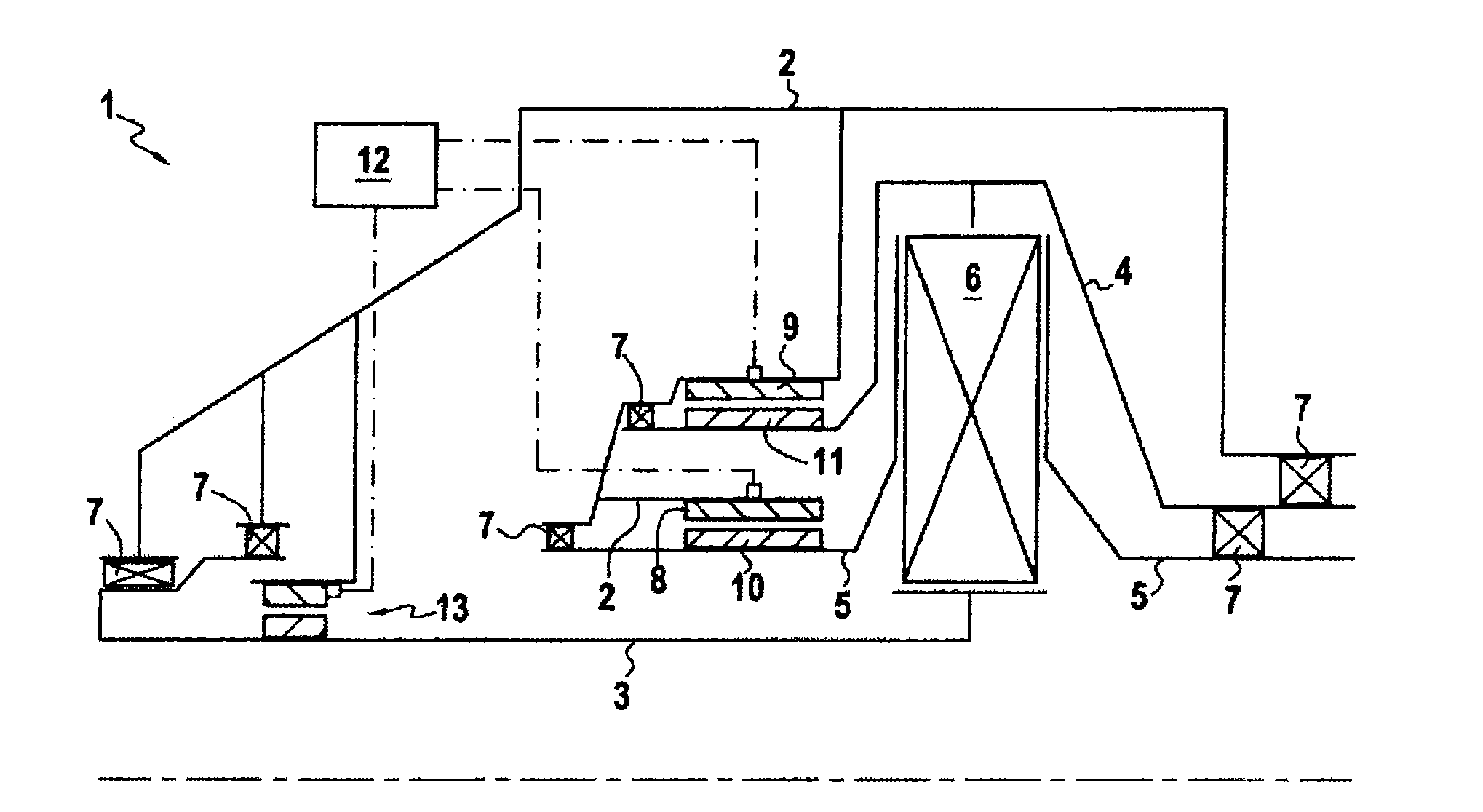
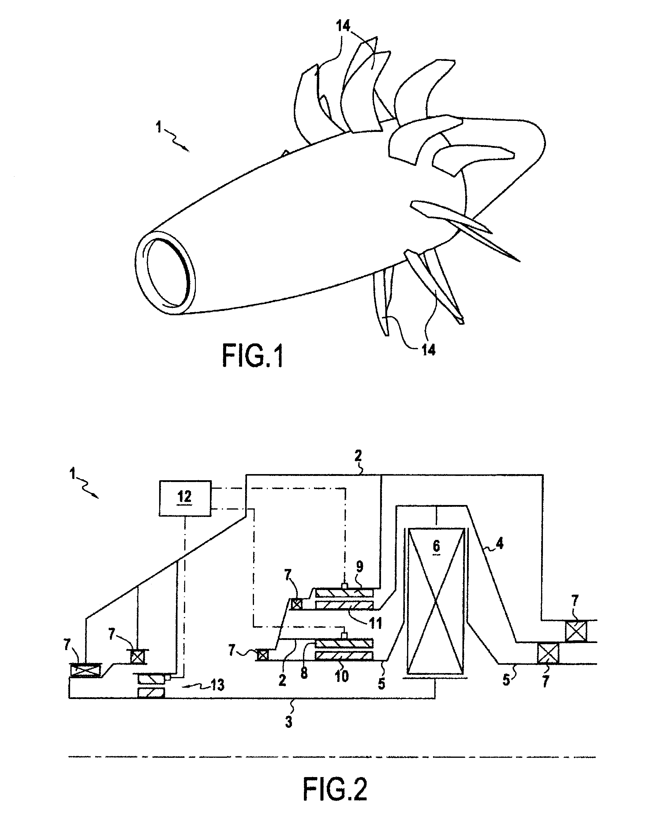
[0038]FIG. 1 gives a perspective view of an aircraft engine 1 illustrated very schematically. The engine 1 is an engine of non-ducted fan type having two counter-rotating rotary supports. Each rotary support carries blades 14. The view in FIG. 2 schematically illustrates the part of the engine 1 at the Power Gear Box allowing conversion of the rotation of a main shaft to rotation of the rotary supports in two opposite directions.

[0039]The engine 1 comprises a fixed part 2 and a main shaft 3 driven in rotation, for example a gas turbine. The engine 1 also comprises a rotary support 4 and a rotary support 5. Bearings 7 allow the rotation of the main shaft 3 and of the rotary supports 4 and 5 relative to the fixed part 2.

[0040]A Power Gear Box 6 connects the main shaft 3 to the rotary support 4 and the rotary support 5. More specifically, when the main shaft 3 rotates in a first direction, the Power Gear Box 6 drives the rotary support 5 in the same first direction and the rotary suppo...


PUM


Abstract

An apparatus including a fixed part, a rotary support configured to be driven in rotation relative to the fixed part, at least one item of electrical equipment carried by the rotary support, and a power supply device configured to supply electrical energy to the electrical equipment. The power supply device includes an asynchronous machine including a stator fixed to the fixed part and a rotor carried by the rotary support, and an excitation device. The stator includes an electrical circuit including at least one switch configured to switch between an open state in which the electrical circuit is open and a closed state in which the electrical circuit is closed. The rotor includes at least one winding connected to the electrical equipment. The excitation device is configured to provide a reactive current to the electrical circuit of the stator or to the winding of the rotor.

Description

BACKGROUND OF THE INVENTION[0001]The invention concerns the supply of electrical energy to electrical equipment carried by a rotary support. In particular, the invention relates to the supply of electrical energy to electrical equipment carried by a rotor of an aircraft engine.[0002]It is known to equip the blades carried by a rotor of an aircraft engine with a de-icing device, comprising heating resistances intended to prevent the formation of ice. To supply power to said de-icing device, electrical energy must be transmitted towards the rotor.[0003]For this purpose, typically a brush device is used. However, brush devices are generally little reliable and subject to rapid wear. They therefore require regular maintenance. In addition, they are generally heavy and cumbersome and may give rise to problems of compatibility with surrounding oils.[0004]It is also known to transmit electrical energy towards the rotor via a rotating transformer. When the power to be transmitted is high, a...

Claims


Application Information

Patent Timeline
IPC IPC(8): H02K7/18B64D15/00
CPCB64D15/12B64D2027/026H01F38/18H02P2101/30B64D15/00H02K7/1823H02P9/46
Inventor DE WERGIFOSSE, ERICDUVAL, CEDRIC
Owner SAFRAN ELECTRICAL & POWER
Why Eureka
Try Eureka