
Adjustable Camshaft

a camshaft and adjustment technology, applied in the direction of valve details, valve arrangements, valve drives, etc., can solve the problems of high complexity and relatively high number of components used

Active Publication Date: 2013-05-02
NEUMAYER TEKFOR ENG GMBH
View PDF1 Cites 30 Cited by
  • Summary
  • Abstract
  • Description
  • Claims
  • Application Information

AI Technical Summary

Benefits of technology

The present invention provides an adjustable camshaft with cams and cam contours that have different widths. This allows for cam packages to be displaced outside of the base circle of a cam, even if one cam is operating a valve at the time. Multiple adjusting elements can also be used to individually or groups of cam packages. The cams and cam contours can be adjusted and slid along the camshaft's long axis, making it possible to control and adjust multiple cam packages simultaneously.

Problems solved by technology

In addition, the number of components used is relatively high, which is associated with high complexity.

Method used


Image

  • Adjustable Camshaft
  • Adjustable Camshaft
  • Adjustable Camshaft

Examples


Embodiment Construction

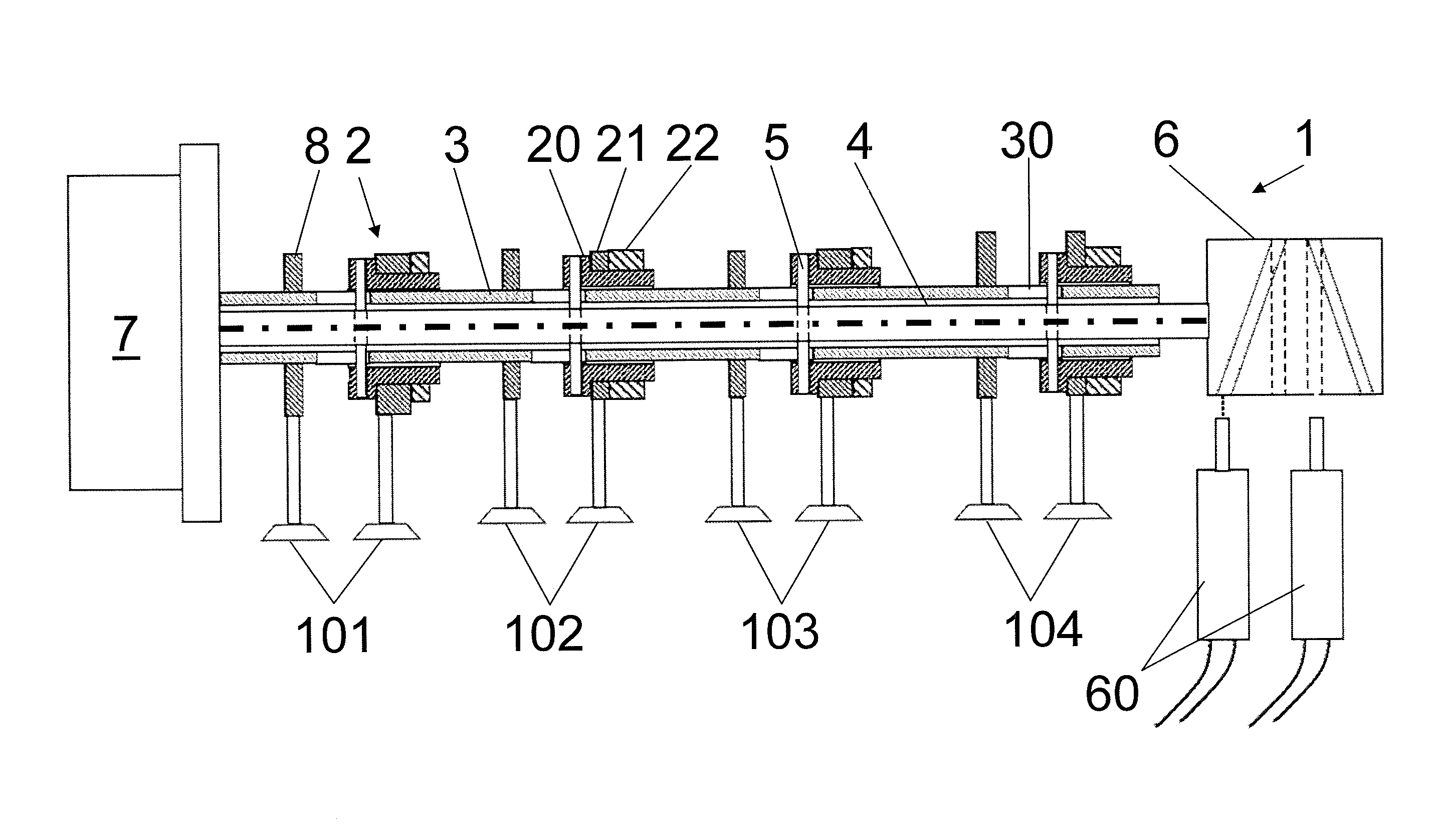
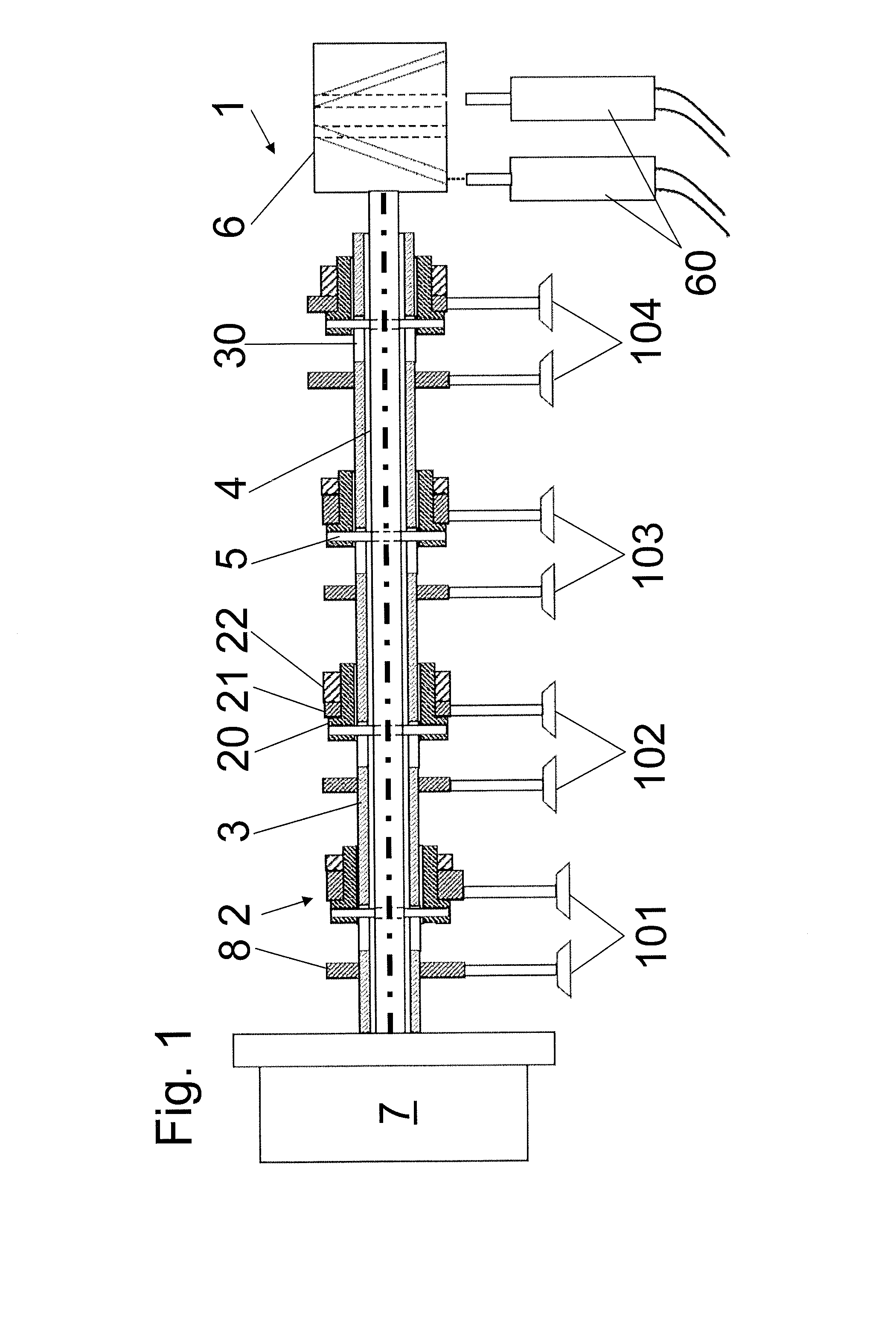
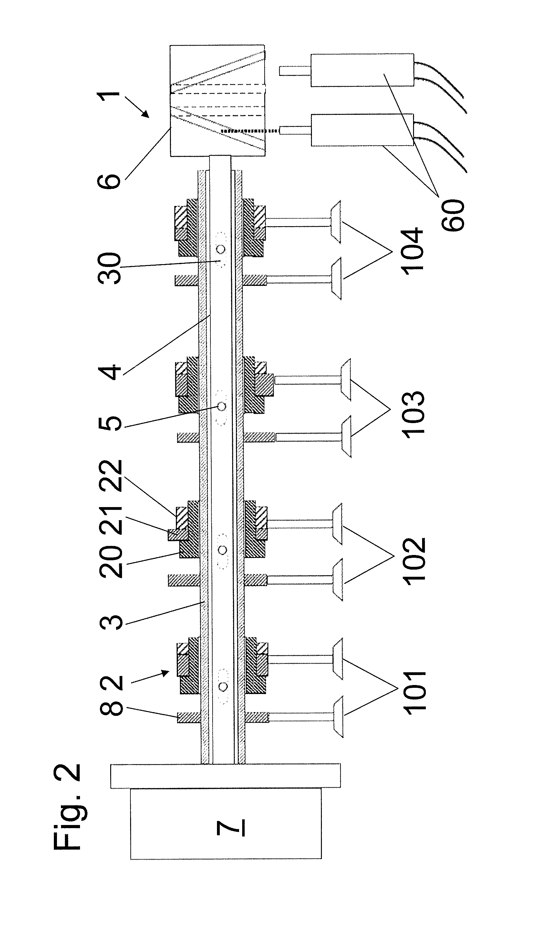
[0037]FIG. 1 illustrates a camshaft 1 according to the invention, intended in this case to control the valves of four cylinders. The invention can also be used in engines having another number of cylinders. Two valves in this case are functionally assigned to each cylinder—not illustrated here—including the valves of the first cylinder 101, the second cylinder 102, the third cylinder 103, and the fourth cylinder 104. In this configuration, one single cam 8 on the camshaft 1 is functionally assigned to each valve—illustrated on the left in this case—said cam being attached to the shaft 3 and fixed in the axial dimension. For each of the other valves—illustrated on the right—one cam package 2 is included which particularly enables a modification of the valve lift.

[0038]In a further variant, which is not illustrated here, it is possible for both valves of a cylinder to be controlled differently according to the invention by a modification of the cams. By way of example, the camshaft 1 ...


PUM


Abstract

An adjustable camshaft having at least one shaft, and having at least one cam package which has at least two different cams and / or cam contours. According to the invention, the cams and / or the cam contours of the cam packages have different widths.

Description

CROSS REFERENCE TO RELATED APPLICATIONS[0001]This application is a continuation of international patent application no. PCT / DE2011 / 001205, filed Jun. 11, 2011, designating the United States of America and published in German on Jan. 19, 2012 as WO 2012 / 006992, the entire disclosure of which is incorporated herein by reference. Priority is claimed based on Federal Republic of Germany patent application no. DE 10 2010 025 100.3, filed Jun. 25, 2010, the entire disclosure of which is likewise incorporated herein by reference.BACKGROUND OF THE INVENTION[0002]The invention relates to an adjustable camshaft, having at least one shaft, and having at least one cam package which comprises at least two different cams and / or cam contours.[0003]A camshaft includes at least one support element, also called a tube or shaft, and at least one cam. For applications in engines, camshafts serve as a part of the valve operating mechanism, wherein the support element rotates about its longitudinal axis....

Claims


Application Information

Patent Timeline
Patent Type & Authority Applications(United States)
IPC IPC(8): F01L1/34
CPCF01L1/04F01L2013/0052F01L1/34F01L13/0036
Inventor WEINMEISTER, ROMAN
Owner NEUMAYER TEKFOR ENG GMBH
Learn More