Evaporator unit

Inactive Publication Date: 2009-04-30
DENSO CORP
View PDF7 Cites 9 Cited by
  • Summary
  • Abstract
  • Description
  • Claims
  • Application Information

AI Technical Summary

Benefits of technology

[0005]In view of the foregoing problems, it is an object of the present invention to improve the

Problems solved by technology

Therefore, the productivity of the evaporator unit may be deteriorated, and the manufacturing cost of the evaporator unit may be increased.
Furthermore, the ejector is difficult to be used for ev

Method used


Image

  • Evaporator unit
  • Evaporator unit
  • Evaporator unit

Examples


first embodiment

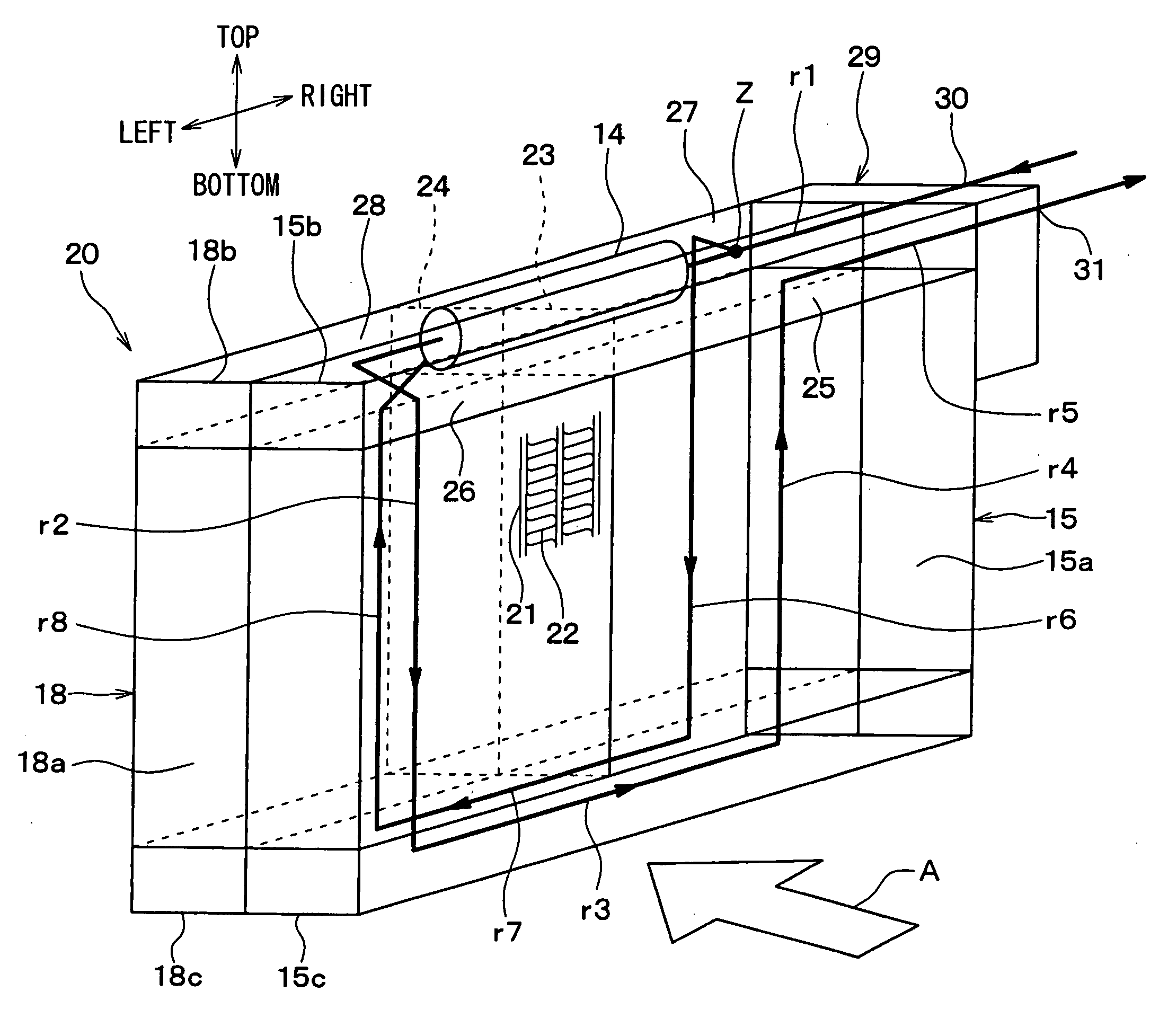
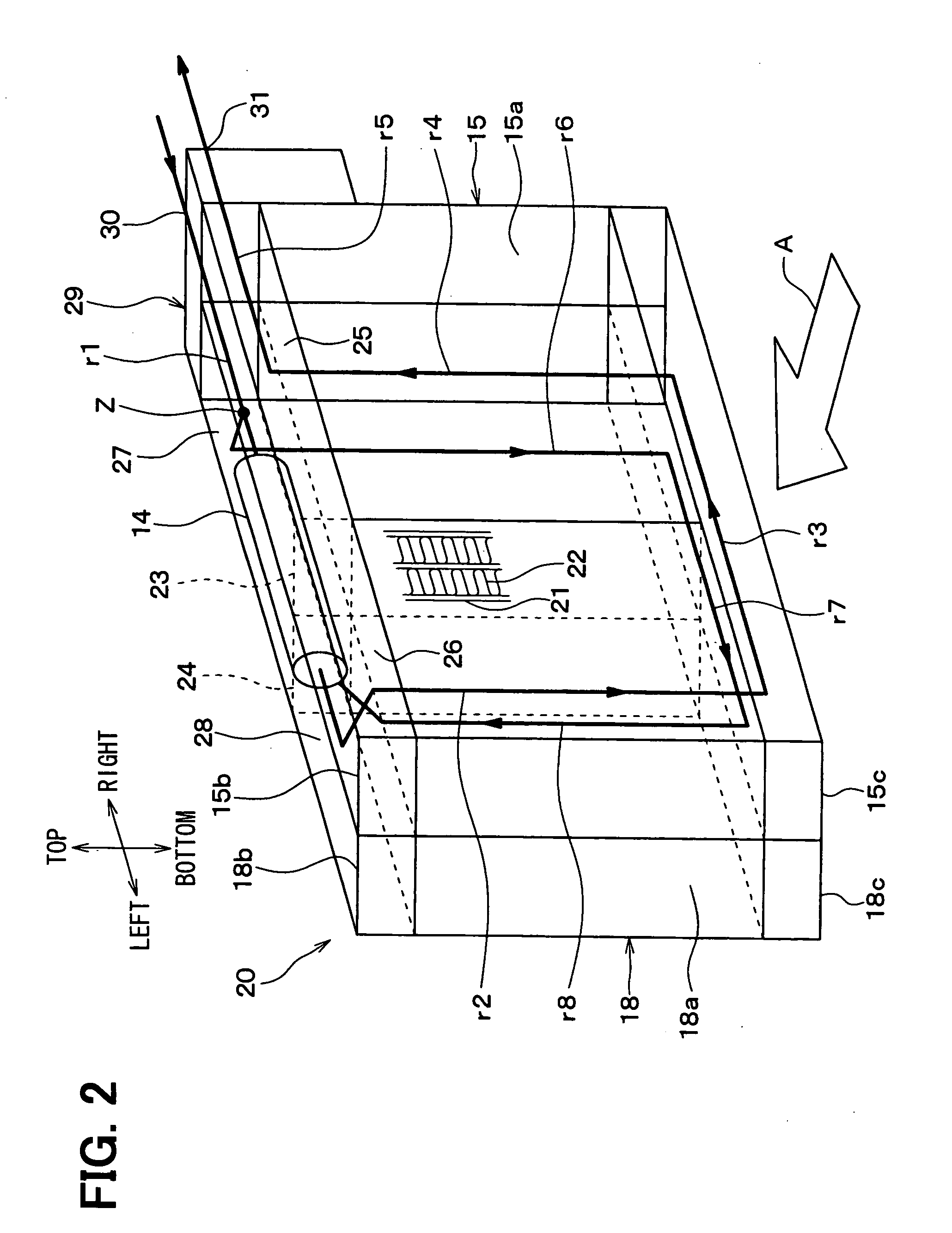
[0042]A first embodiment of the present invention and modifications of the first embodiment will be described below with reference to FIGS. 1 to 5. In the present embodiment, an evaporator unit for an ejector refrigerant cycle device and an ejector refrigerant cycle device using the evaporator unit will be now described. For example, the evaporator unit is an ejector-equipped evaporator unit for a refrigerant cycle device.

[0043]The evaporator unit is connected to other components of the refrigerant cycle device, including a condenser (refrigerant cooler), a compressor, and the like, via piping. The evaporator unit of the present embodiment is used for application to an indoor equipment (i.e., evaporator) for cooling air. However, the evaporator unit may be used as an outdoor equipment in other examples.

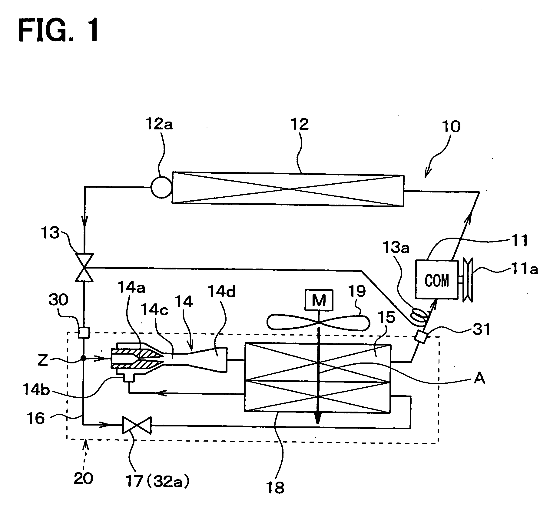
[0044]In an ejector refrigerant cycle device 10 shown in FIG. 1, a compressor 11 for drawing and compressing refrigerant is driven by an engine for vehicle traveling (not shown) via a...

second embodiment

[0129]In the above-described first embodiment, the nozzle portion 14a and the mixing portion 14c are located separately from each other. However, in the second embodiment, as shown in FIG. 6, the nozzle portion 14a and the mixing portion 14c are connected in the ejector 14.

[0130]A pipe portion 34 is formed at a tip end portion (downstream end portion) of the nozzle portion 14a. The pipe portion 34 is inserted into an inlet portion of the mixing portion 14c, and an outer peripheral surface of the pipe portion 34 is brazed onto an inner peripheral surface of the mixing portion 14c in the inserted portion, thereby air-tightly fixing the pipe portion 34 to the mixing portion 14c of the ejector 14. In this case, assemble accuracy such as a coaxial accuracy between the mixing portion 14c and the nozzle portion 14a can be improved in the ejector 14.

[0131]A hole is provided in a pipe wall of the pipe portion 34 at a position outside of the mixing portion 14c so as to define and construct th...

third embodiment

[0135]A third embodiment of the present invention will be described with reference to FIGS. 7 and 8. In the above-described first embodiment, the ejector 14 is located inside the upper header tank 18b of the second evaporator 18. However, in the third embodiment, a separate tank 40 is located separately from the upper header tanks 15b, 18b, to accommodate therein the ejector 14. That is, the separate tank 40 is located outside the upper header tanks 15b and 18b at a valley portion between the upper header tanks 15b and 18b to contact both the upper header tanks 15b and 18b. The separate tank 40 can be used exclusively for the ejector 14.

[0136]The separate tank 40 has a cylindrical shape extending in the tank longitudinal direction of the upper header tanks 15b, 18b. The separate tank 40 is located at the valley portion between the upper header tanks 15b and 18b, and is integrally brazed to the outer surfaces of the upper header tanks 15b, 18b. In the third embodiment, the inner diam...


PUM


Abstract

In an evaporator unit for a refrigerant cycle device, an evaporator is connected to an ejector to evaporate refrigerant to be drawn into a refrigerant suction port of the ejector or the refrigerant flowing out of the outlet of the ejector. The evaporator includes a plurality of tubes in which the refrigerant flows, and a tank configured to distribute the refrigerant into the tubes or to collect the refrigerant from the tubes. The ejector is located in the tank, and the nozzle portion is brazed to the tank to be fixed into the tank. The tank may be a header tank directly connected to the tubes or may be a separate tank separated from the header tank.

Description

CROSS REFERENCE TO RELATED APPLICATION[0001]This application is based on Japanese Patent Applications No. 2007-276241 filed on Oct. 24, 2007, and No. 2008-193153 filed on Jul. 28, 2008, the contents of which are incorporated herein by reference in its entirety.FIELD OF THE INVENTION[0002]The present invention relates to an evaporator unit for a refrigerant cycle device with an ejector.BACKGROUND OF THE INVENTION[0003]JP-A-2007-192465 (corresponding to US 2007 / 0163294 A1) proposes an evaporator unit for a refrigerant cycle device with an ejector. In the evaporator unit, the ejector having a refrigerant decompressing function and a refrigerant circulating function is located inside a tank of an evaporator so that the ejector and the evaporator are integrated. Thus, the ejector and the evaporator can be mounted as an integrated unit, thereby improving a mounting performance of the refrigerant cycle device with the ejector.[0004]In the evaporator unit, after an evaporator body is integr...

Claims


Application Information

Patent Timeline
IPC IPC(8): F25B1/06F25B39/02
CPCF25B39/02F25B41/00F25B2500/18F25B2500/01F25B2341/0011B60H2001/3298
Inventor BRODIE, BRADLEYTAKANO, YOSHIAKIITO, SHIGEKIGOCHO, MIKANISHIJIMA, HARUYUKINAKAMURA, TOMOHIKO
Owner DENSO CORP
Why Eureka
Try Eureka