Thermal transfer printer

a printer and thermal transfer technology, applied in the field can solve the problems of thermal transfer printers that cannot cut printing paper in various paper widths

Active Publication Date: 2015-08-06
MITSUBISHI ELECTRIC CORP
View PDF2 Cites 6 Cited by
  • Summary
  • Abstract
  • Description
  • Claims
  • Application Information

AI Technical Summary

Benefits of technology

[0006]It is an object of the present invention to provide a thermal tra

Problems solved by technology

However, a position of the slitter is fixed in the thermal transfer printer disclosed in Japanese Patent Application L

Method used


Image

  • Thermal transfer printer
  • Thermal transfer printer
  • Thermal transfer printer

Examples


first preferred embodiment

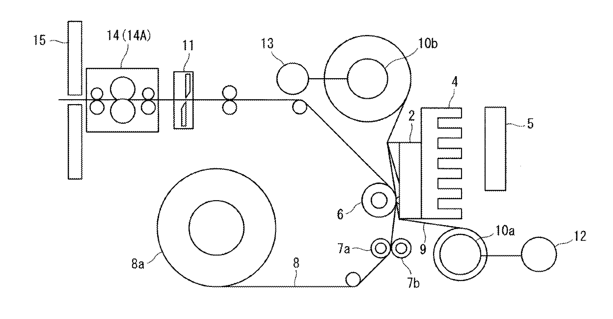
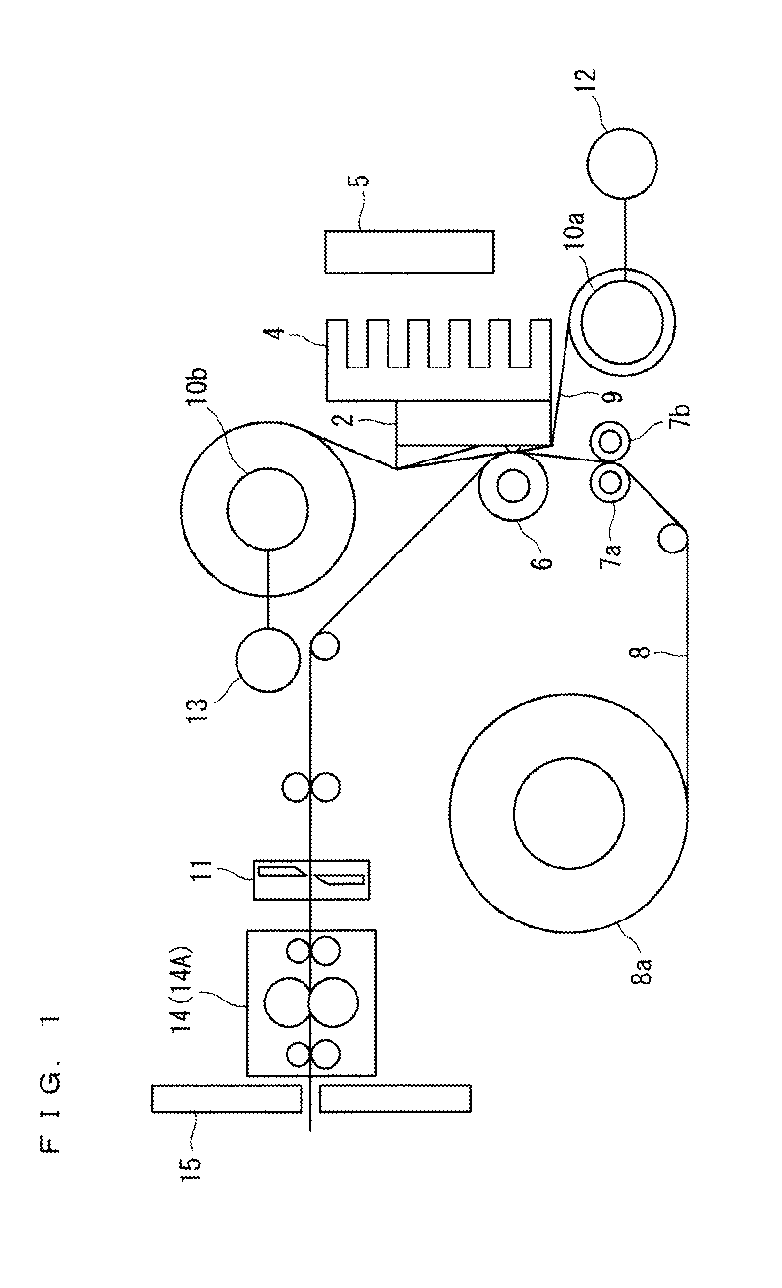
[0016]FIG. 1 is a diagram illustrating a configuration of a thermal transfer printer according to this preferred embodiment. As shown in FIG. 1, the thermal transfer printer of the preferred embodiment includes, as a printing section for performing printing, a thermal head 2 that heats an ink sheet 9 and a platen roller 6 that presses a printing paper 8 against the ink sheet 9 between the thermal head 2 and the platen roller 6. A heat sink 4 that dissipates heat from the thermal head 2 is installed to the thermal head 2. A cooling fan 5 cools the heat sink 4.

[0017]The thermal transfer printer includes a grip roller 7a and a pinch roller 7b that draw the printing paper 8 from a printing paper roll 8 to transport the printing paper 8. The pinch roller 7b is pressed against the grip roller 7a via the priming paper 8. The ink sheet 9 is unwound from an ink unwinding reel 10b. The ink sheet 9 is wound around an ink winding reel 10a after being used for the printing. The ink sheet 9 has p...

second preferred embodiment

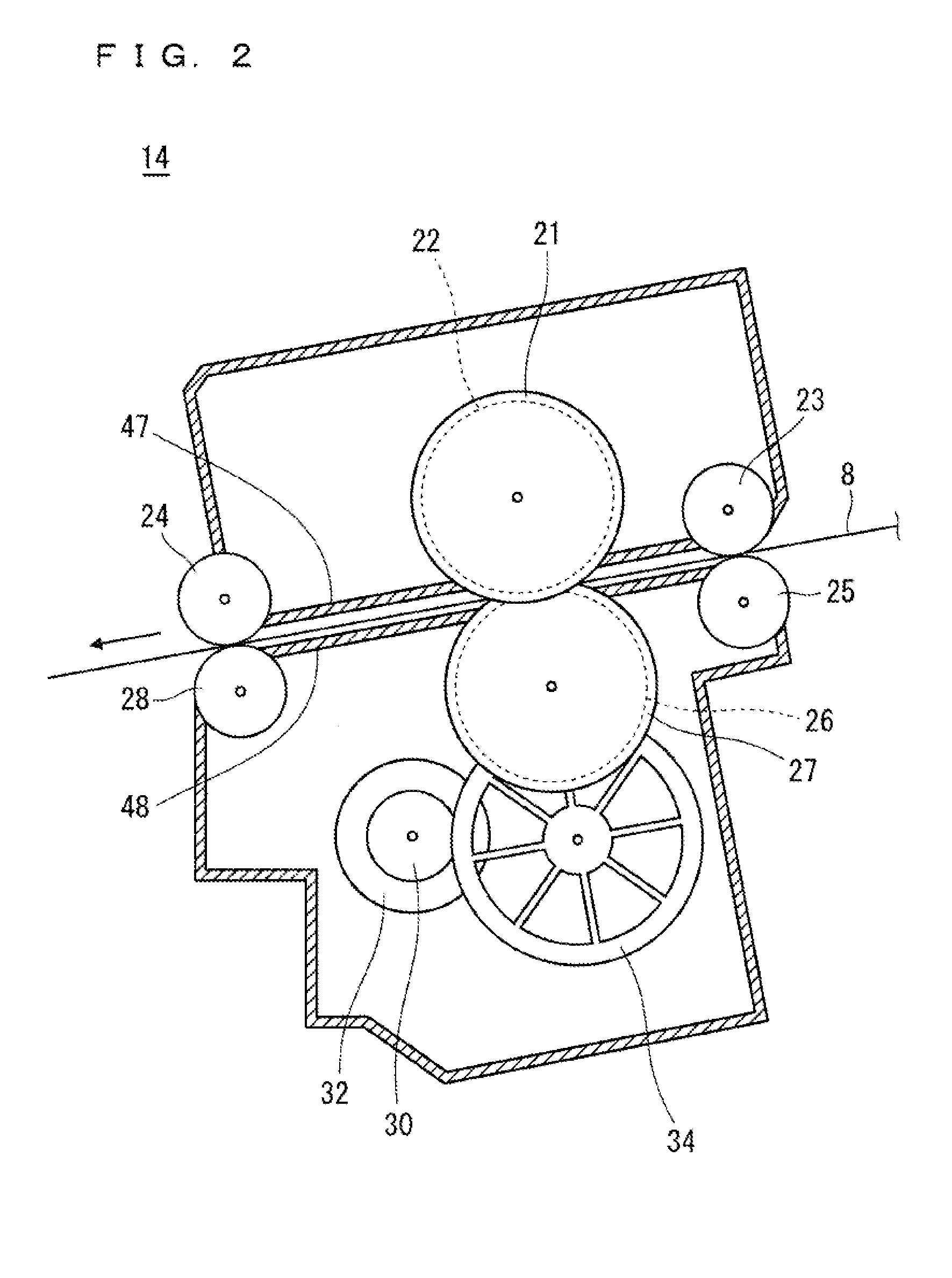
[0052]FIG. 7 is a front view of a slitter section 14A of a thermal transfer printer according to this preferred embodiment. The configuration except for the position adjustment mechanism of the slitter section 14A of the thermal transfer printer in the preferred embodiment is the same as the configuration of the slitter section 14 in the first preferred embodiment. Thus, description about the transport mechanism of the slitter section 14A of the thermal transfer printer in this preferred embodiment will be omitted. The same components as those described in the first preferred embodiment are denoted by the same references.

[0053]The slitter section 14A of the preferred embodiment includes a pair of a pulley 53 and a pulley 54, a belt 51 that loops over the pulley 53 and the pulley 54, the frame 40 that is fixed to the belt 51 and moves the transport direction (namely, paper width direction) of the belt 51, and a motor 57 that rotationally moves the pulley 53.

[0054]The slitter section ...


PUM


Abstract

A thermal transfer printer according to the present invention includes a printing section that thermally transfers an ink of an ink sheet to printing paper for performing printing and a slitter section that cuts, in a paper transport direction, the printing paper after the printing by the printing section. The printing section includes a thermal head and a platen roller pressed against the thermal head. The slitter section is capable of adjusting a cutting position for cutting the printing paper.

Description

BACKGROUND OF THE INVENTION[0001]1. Field of the Invention[0002]The present invention relates to a thermal transfer printer, and more particularly, to a thermal transfer printer that cuts printing paper in a paper transport direction.[0003]2. Description of the Background Art[0004]Thermal transfer printers that draw printing paper from a paper roll for performing printing typically include cutters for cutting the printing paper after the printing in a direction orthogonal to a paper transport direction (namely, printing-paper width direction). Thermal transfer printers are also known that include slitters for cutting printing paper in parallel to a paper transport direction (for example, see Japanese Patent Application Laid-Open No, 2007-111999).[0005]However, a position of the slitter is fixed in the thermal transfer printer disclosed in Japanese Patent Application Laid-Open No. 2007-111999, so that the thermal transfer printer fails to cut the printing paper in various paper width...

Claims


Application Information

Patent Timeline
IPC IPC(8): B41J11/70
CPCB41J11/70B26D2001/0066B41J11/68B26D1/245B26D5/06
Inventor YAMAMOTO, YOSHIFUMIITO, AKIHITO
Owner MITSUBISHI ELECTRIC CORP
Why Eureka
Try Eureka