Modular Delivery System

a delivery system and module technology, applied in conveyors, furnace components, lighting and heating apparatus, etc., can solve the problems of not being able to transport or deliver cooled samples, especially deep freeze samples, and achieve the effect of removing and replacing the lid

Active Publication Date: 2014-12-30
ASKION
View PDF14 Cites 9 Cited by
  • Summary
  • Abstract
  • Description
  • Claims
  • Application Information

AI Technical Summary

Benefits of technology

[0023]The second switching element can also be, for example, a pin, a horizontally oriented plate or a plurality of pins or pegs arranged adjacently at one height. The Maltese cross is prevented from rotating by more than one quarter revolution by a plate or by adjacently arranged pins or pegs.
[0026]It is extremely advantageous when an arrangement of a first switching element and a second switching element is followed in turn by a second switching element and another first switching element. In so doing, a first switching element and a second switching element is arranged on each side of the delivery position, and the second switching element is arranged closer to the delivery position than the first switching element in each instance. As a result of this kind of arrangement of a total of four switching elements, a trolley can be delivered to the delivery position from different directions. Accordingly, the delivery position can be set midway in the guide rail, for example. The trolley can be delivered to this delivery position from both sides so that the times for a delivery can be kept short and the existing trolleys can be used efficiently. By means of the arrangement of four switching elements, the trolley always reaches the delivery position in the unlocked condition and is always in the locked condition after passing the arrangement of switching elements, that is, regardless of whether it was previously locked or unlocked. By locked condition is meant that the long arms are oriented vertically. If the delivery table is present on the trolley, the locking element prevents this delivery table from being removed from the trolley. Correspondingly, an unlocked condition exists when the short arms are oriented vertically.
[0028]The delivery table can have movement elements such as, e.g., wheels, rollers or rolls on which the delivery table rolls on the delivery path. In an advantageous embodiment, the arrangement of the movement elements is selected in such a way that an assembly-dependent gap which may possibly be present between the trolley and the delivery path can be bridged without tilting the trolley out of a specified, e.g., horizontal, position. Accordingly, at least three movement elements can be provided at the delivery table and their mutual distances with respect to one another are selected in such a way that the center of mass of the delivery table preferably lies over the axis of the middle movement element, and the distances between the axis of the middle movement element and the respective axes of the other movement elements are greater than the gap. Arranging the movement elements in this way ensures that the delivery table will always stand on at least two movement elements and prevents a tilting of the delivery table. In a preferred embodiment of the delivery table, the delivery table has four wheels as movement elements on two of its sides in each instance. The gap which may be present must be bridged when the delivery table is delivered to the end position from a trolley located at the delivery position and when delivered from the end position back to the trolley. The described arrangement of the movement elements makes it possible to allow gaps of different widths during assembly of the modular delivery system. This facilitates the use of standardized parts of the delivery path without requiring exactly fitting connections between guide rails, trolley and delivery path by time-consuming adjustment and custom fabrication, so that a greater flexibility of the modular delivery system is achieved.
[0031]For this purpose, the delivery table can have at least one cam and the portal can have at least one slotted link, the cam and slotted link being configured and arranged in such a way that the cam engages in the slotted link at the start of the expanse and exits the slotted link at the end of the expanse. When the cam exits the slotted link, the delivery table is movable forward under the portal and a free access to the delivery table and any object transported thereon is ensured. The transmission of force from the delivery table to the portal takes place from the cam to the slotted link. A plurality of cams and slotted links can be provided for a more uniform and a symmetrical transmission of force. The expanse can additionally be limited by stops of the portal which prevent an overshooting of the expanse. Means for holding the portal, e.g., magnets or a catch mechanism between portal and stop, can be provided at the higher end of the expanse.
[0036]It has proven expedient when the drive of the transporting belt has a torque sensor, for example, to press the delivery table with static force against a fixed end stop or to prevent consequential damage in the event of malfunctions or technical defects by means of an intentional emergency stop.
[0042]Due to the ability to remove and replace a lid, the modular delivery system according to the invention is particularly suitable for delivery of cooled and frozen samples. For example, medical, biochemical or chemical samples can be delivered to a plurality of end positions. Further, the samples can also be processed, exchanged or simply removed at the end positions. The delivery table is deliverable to the respective end positions depending on the sample currently placed on or in an object and on the need for the sample at different end positions. Due to a defined orientation of the object, the position of samples provided in the object is also unambiguously defined at all times so that safe removal and insertion can be carried out without errors. Further, reading devices for sensing marks on the samples, e.g., applied barcodes, can be provided for verifying the identity of a sample that has been removed or is to be inserted.

Problems solved by technology

The described delivery system is disadvantageous in that a trolley must remain at the end position during loading and unloading and is not available for other purposes.
The modular delivery system disclosed in U.S. Pat. No. 6,308,818 B1 is also not suitable for transporting or delivering cooled, especially deep-frozen, samples, e.g., for medical purposes, because there is no assurance that the cold chain will be maintained.

Method used


Image

  • Modular Delivery System
  • Modular Delivery System
  • Modular Delivery System

Examples


Embodiment Construction

[0054]The particulars shown herein are by way of example and for purposes of illustrative discussion of the embodiments of the present invention only and are presented in the cause of providing what is believed to be the most useful and readily understood description of the principles and conceptual aspects of the present invention. In this regard, no attempt is made to show structural details of the present invention in more detail than is necessary for the fundamental understanding of the present invention, the description taken with the drawings making apparent to those skilled in the art how the several forms of the present invention may be embodied in practice.

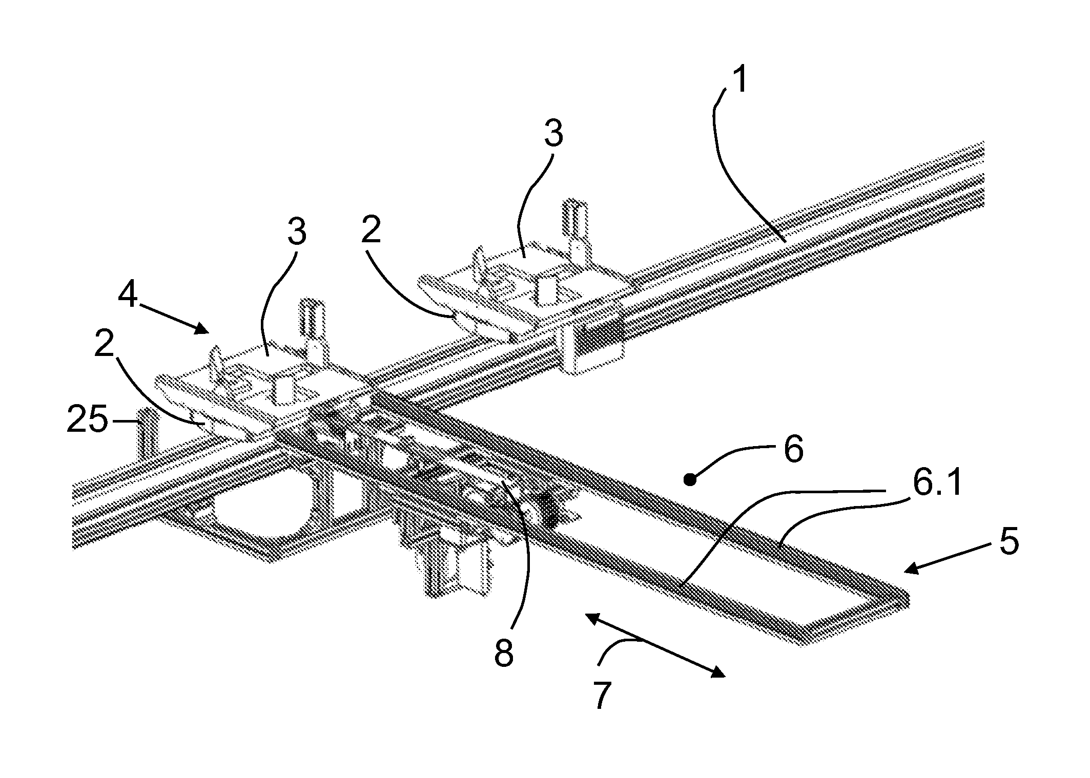
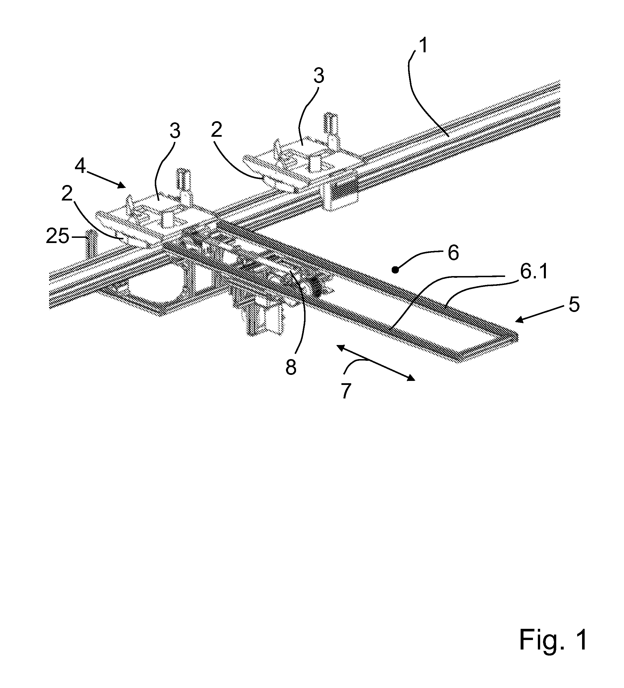
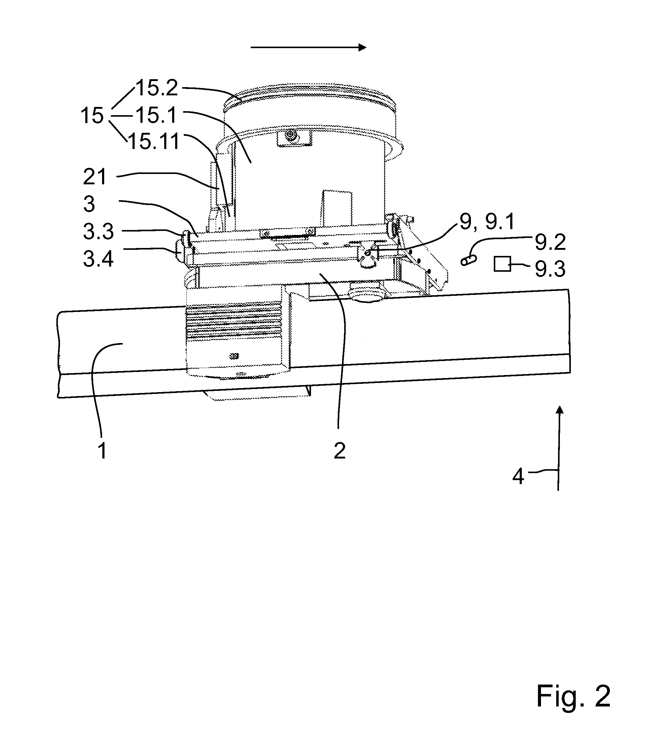
[0055]FIG. 1 shows a guide rail 1, two trolleys 2, each with a delivery table 3, and a delivery station 6 as key components of a modular delivery system according to the invention.

[0056]The trolleys 2, together with the delivery tables 3 provided on the trolleys 2, are movable along the guide rail 1 and deliverable to a d...


PUM


Abstract

Disclosed is a modular delivery system that includes a guide rail (1) with which is associated at least one delivery station (6) for delivering an object to an end position (5), and a trolley (2) which is movable along the guide rail (1) for transporting an object. A delivery position (4) of the trolley (2) is determined by each associated delivery station (6), and the trolley (2) is repeatedly deliverable to at least one of the delivery positions (4). The trolley (2) has a delivery table (3) which can be placed on and removed from the trolley (2) horizontally, and the delivery table (3) is transferable from every delivery position (4) to the associated end position (5) and from every end position (5) to the associated delivery position (4).

Description

CROSS-REFERENCE TO RELATED APPLICATIONS[0001]The present application claims priority under 35 U.S.C. 119 of German Patent Application No. 10 2012 104 539.9, filed May 25, 2012, the entire disclosure of which is expressly incorporated by reference herein.BACKGROUND OF THE INVENTION[0002]1. Field of the Invention[0003]The invention is directed to a modular delivery system for the delivery of objects to at least one end position using a rail system such as is known generically from U.S. Pat. No. 6,308,818 B1, the entire disclosure of which is incorporated by reference herein.[0004]2. Discussion of Background Information[0005]Delivery systems are known, for example, for use in the production, assembly or packaging of products or in the warehousing of objects such as, e.g., tools, consumables or merchandise.[0006]It is particularly convenient when the delivery system is formed modularly so that the delivery system can be easily adapted to different local conditions, workload capacities a...

Claims


Application Information

Patent Timeline
Patent Type & Authority Patents(United States)
IPC IPC(8): B61B5/00B65G35/06B61B13/04B65G47/84
CPCB61B5/00Y02T30/40B65G35/06B61B13/04Y02T30/00
Inventor BUERGERMEISTER, DANIELKAESTNER, ANDREAS
Owner ASKION
Why Eureka
Try Eureka