Energy absorber

a technology of energy absorber and splint, which is applied in the direction of shock absorber, safety belt, building scaffold, etc., can solve the problems of significant distance, inability to protect workers, and inability to absorb shock,

Inactive Publication Date: 2013-05-02
D B IND
View PDF0 Cites 20 Cited by
  • Summary
  • Abstract
  • Description
  • Claims
  • Application Information

AI Technical Summary

Benefits of technology

[0005]In one embodiment, an energy absorber is provided. The energy absorber includes a first energy absorbing webbing, a second energy absorbing webbing and a plurality of connecting fibers. The plurality of connecting fibers couple at least a portion of the first energy absorbing webbing to at least a portion of the second energy absorbing webbing. The plurality of connecting fibers are configured and arranged to form at least two different tear strength areas in the at least one portion of the first energy absorbing webbing coupled to the at least one portion of the second webbing. The at least two different tear strength areas having select tear strengths.
[0006]In another embodiment, another energy absorber is provided. The energy absorber includes a first energy absorbing webbing, a second energy absorbing webbing, a plurality of connecting fibers and first and second attaching webbings. The first energy absorbing webbing has a length that is defined between a first end and a second end. The first energy absorber further has a first mid portion that is centrally located between the first end and the second end. The second energy absorbing webbing is positioned along the length of the first energy absorber. The second energy absorbing webbing has a length that is defined between a first and second end. The second energy absorbing webbing has a second mid portion that is centrally located between the first and the second end of the second energy absorbing webbing. The second mid portion of the second energy absorbing webbing is aligned with the first mid portion of the first energy absorbing webbing. The plurality of connecting fibers connect the first energy absorbing webbing to the second energy absorbing webbing. In particular, the plurality of connecting fibers connect the first energy absorbing webbing to the second energy absorbing webbing between respective first ends of the first and second energy absorbing webbings and the respective mid portions and between respective second ends of the first and second energy absorbing webbings and the respective mid portions. The plurality of connecting fibers are configured and arranged to form at least two different tear strength areas in the first and second energy absorbing webbings. The first attaching webbing is coupled to the first mid portion of the first energy absorber and the second attaching webbing is coupled to the second mid portion of the second energy absorber.
[0007]In still another embodiment, a lifeline system is provided. The lifeline system includes a lifeline and an energy absorber. The lifeline is configured and arranged to be coupled between a support structure and a safety harness. The lifeline includes a back strap portion and an energy absorber system. The energy absorbing system includes a first webbing, a second webbing, a first attaching webbing, a second attaching webbing and connecting fibers. The second webbing is coupled along a first webbing length of the first webbing. The first attaching webbing is coupled between a first mid portion of the first webbing and a first end of the back strap portion of the lifeline. The second attaching webbing is coupled between a second mid portion of the second webbing and a second end of the back strap portion of the lifeline. The second mid portion of the second webbing is aligned with the first mid portion of the first webbing forming first and second webbing connection portions of generally equal lengths on either side of the respective first and second mid portions of the first and second webbings.
[0008]The connecting fibers couple the first webbing to the second webbing. The connection fibers form a first tear strength area, a second tear strength area and a transition tear area in each of the first and second webbing connection portions of the first and second webbings. The first tear strength area has a tear strength less than the tear strength of the second tear strength area. The transition tear strength area has a tear strength between the first tear strength and the second tear strength. Each first tear strength area is positioned adjacent an associated first and second mid portion of the first and second webbings. The transition tear strength area is further positioned between the first and second tear strength areas.

Problems solved by technology

Injury to the worker can occur when the fall distance, before the lifeline becomes taut, is significant.

Method used


Image

  • Energy absorber
  • Energy absorber
  • Energy absorber

Examples


Embodiment Construction

[0019]In the following detailed description, reference is made to the accompanying drawings, which form a part hereof, and in which is shown by way of illustration specific embodiments in which the inventions may be practiced. These embodiments are described in sufficient detail to enable those skilled in the art to practice the invention, and it is to be understood that other embodiments may be utilized and that changes may be made without departing from the spirit and scope of the present invention. The following detailed description is, therefore, not to be taken in a limiting sense, and the scope of the present invention is defined only by the claims and equivalents thereof.

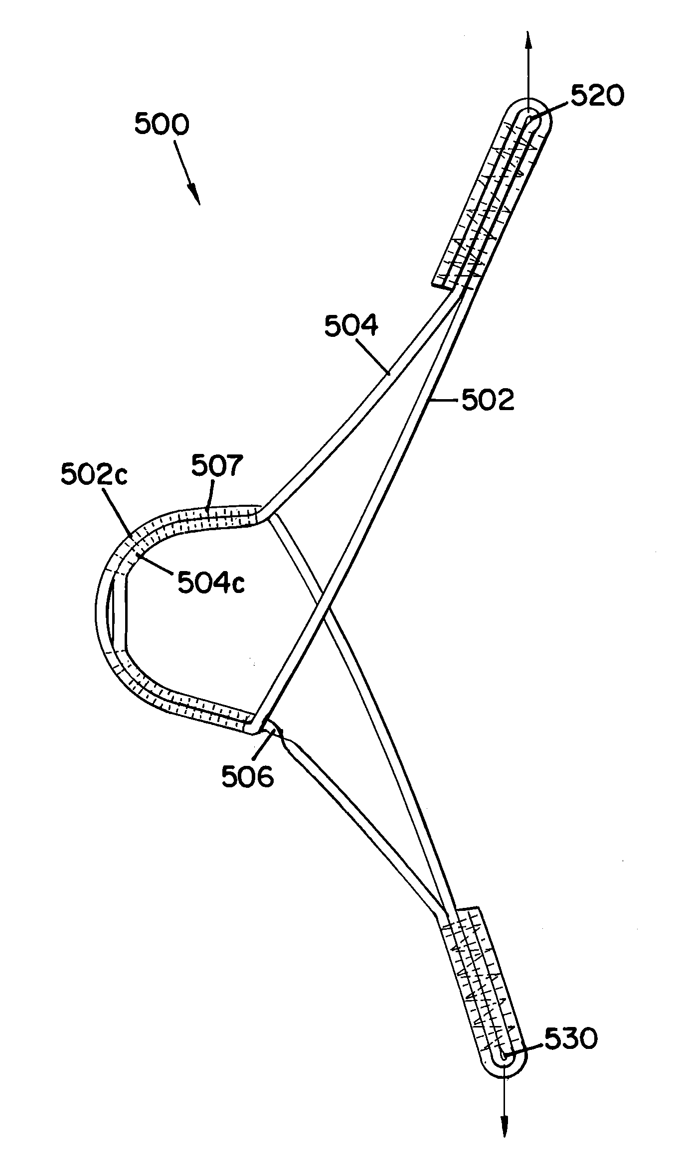
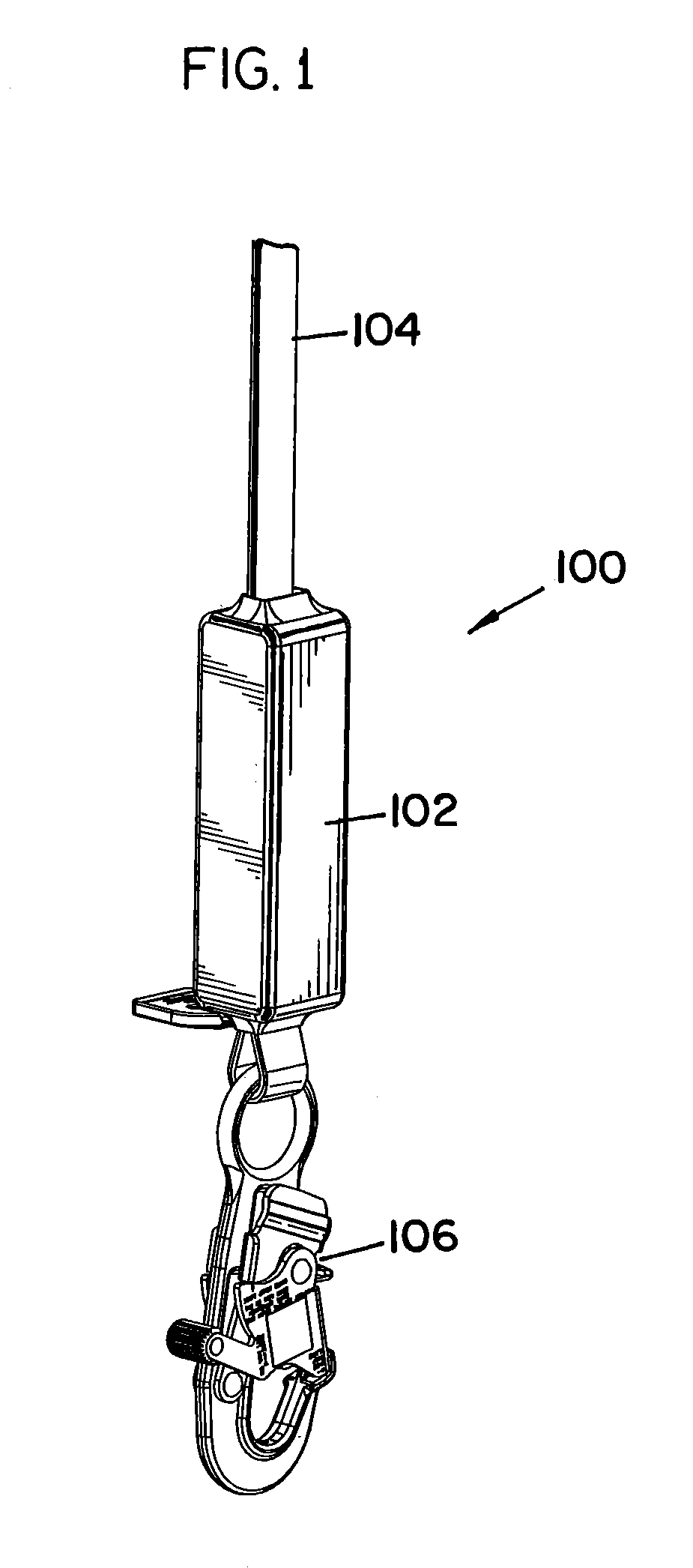
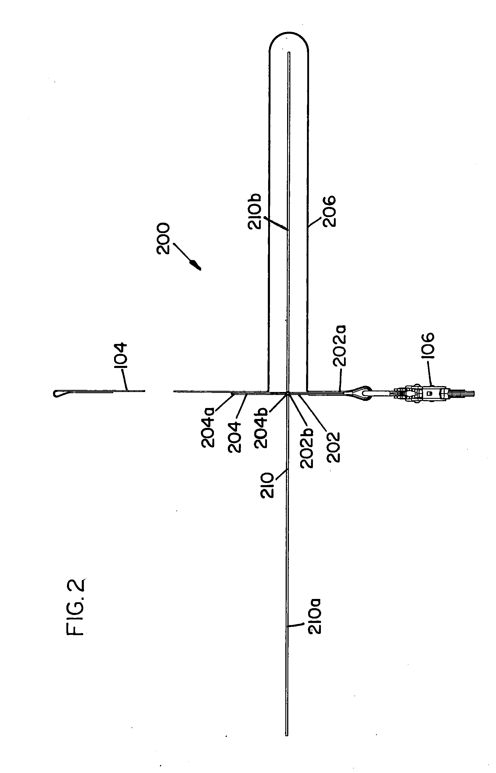
[0020]Embodiments of the present invention provide an energy absorbing system to reduce or prevent an injury when an associated lifeline becomes taut during a fall event. Embodiments of the present invention absorb energy by tearing apart a pair of webbings that are connected together. The pair of webbings ar...


PUM

PropertyMeasurementUnit
lengthaaaaaaaaaa
lengthaaaaaaaaaa
widthaaaaaaaaaa

Abstract

An energy absorber is provided that includes a first energy absorbing webbing, a second energy absorbing webbing and a plurality of connecting fibers. The plurality of connecting fibers couple at least a portion of the first energy absorbing webbing to at least a portion of the second energy absorbing webbing. The plurality of connecting fibers are configured and arranged to form at least two different tear strength areas in the at least one portion of the first energy absorbing webbing coupled to the at least one portion of the second webbing. The at least two different tear strength areas having select tear strengths.

Description

CROSS-REFERENCE TO RELATED APPLICATIONS[0001]This Application claims priority to U.S. Provisional Application Ser. No. 61 / 552,498 same title herewith, filed on Oct. 28, 2011, which is incorporated in its entirety herein by reference.BACKGROUND[0002]To protect workers that have to work at heights, lifelines coupled to safety harnesses donned by a worker are typically used. If a fall event occurs, the lifeline coupled to a support structure limits the fall of the worker. Injury to the worker can occur when the fall distance, before the lifeline becomes taut, is significant. Energy absorbers have been added to lifeline systems to provide a less abrupt stop to help reduce or prevent injuries. An energy absorber absorbs some of the kinetic energy of the falling body.[0003]For the reasons stated above and for other reasons stated below which will become apparent to those skilled in the art upon reading and understanding the present specification, there is a need in the art for an effectiv...

Claims


Application Information

Patent Timeline
Patent Type & Authority Applications(United States)
IPC IPC(8): A62B35/04B32B7/08
CPCA62B35/04F16F7/006
Inventor SCHLANGEN, DAVID A.PERNER, JUDD J.
Owner D B IND
Why Eureka
Try Eureka