Equipment and method for measuring the offset angle of a resolver in a synchronous electric machine

a technology of synchronous electric machines and resolvers, which is applied in the direction of electronic commutators, motors/generators/converter stoppers, dynamo-electric converter control, etc., can solve the problems of inaccurate approaches and greedy calculation time and calculation tim

Inactive Publication Date: 2013-05-02
MICHELIN & CO CIE GEN DES ESTAB MICHELIN +1
View PDF1 Cites 10 Cited by
  • Summary
  • Abstract
  • Description
  • Claims
  • Application Information

AI Technical Summary

Benefits of technology

[0014](ii) energizing the main stator so that the electric machine develops a correction torque making it poss

Problems solved by technology

Such approaches are therefore not precise and

Method used


Image

  • Equipment and method for measuring the offset angle of a resolver in a synchronous electric machine
  • Equipment and method for measuring the offset angle of a resolver in a synchronous electric machine
  • Equipment and method for measuring the offset angle of a resolver in a synchronous electric machine

Examples


Embodiment Construction

[0027]Let us firstly set forth how it is possible to undertake the measurement of the setup error of the rotor of the resolver.

[0028]According to a conventional tactic, a constant current is injected for example into two phases of the stator coil. The rotor, which must be free in rotation, then takes a well defined equilibrium position, the rotor flux aligning naturally with the stator flux produced. For this equilibrium position of the rotor, it is known what ought to be the indication of the position measurement by the resolver and it is therefore possible to deduce therefrom the error between this envisaged measurement and the present measurement. It is this error that will have to be cancelled by the resolver setup operation.

[0029]This scheme exhibits the following drawbacks however. It is necessary to inject significant currents into the stator to obtain a rotor position that is actually well defined, hence potentially significant heating in the course of the setup procedure. F...


PUM


Abstract

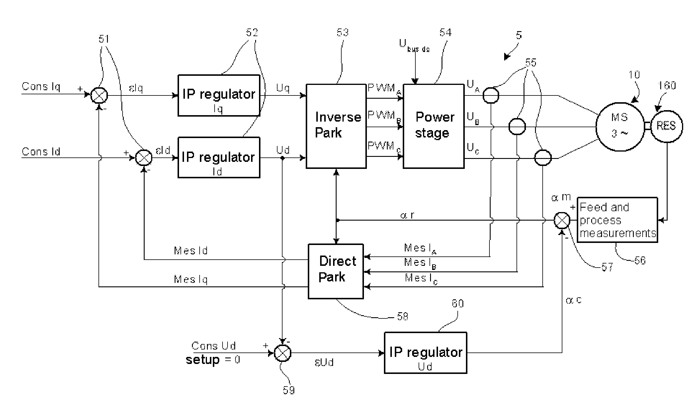
An apparatus for measuring an error in a resolver includes a first calculator that perform an inverse Park transform based on voltages Uq and Ud at an output of PI current regulators, and delivers voltage setpoint signals PWMA, PWMB, PWMC to a power stage via a line on which a DC voltage Ubus-dc is available. The power stage generates a three-phase system of voltages UA, UB, UC for energizing an electric machine. The apparatus also includes a signal processor that provides an angle measurement αm. Based on currents MesIA, MesIB, MesIC of the three phases, and on a rotor angle αr, a second calculator of the device delivers values MesId, MesIq used by the first calculator. A PI voltage regulator delivers an angle αc for correcting the error by regulating a setpoint value for the voltage Ud.

Description

FIELD OF THE INVENTION[0001]The present invention relates to rotating electric machines. The present invention is more particularly aimed at rotating electric machines provided with a resolver, or with any other sensor making it possible to measure an absolute angular position, and the present invention pertains to the initial adjustment of this sensor, for example a resolver.PRIOR ART[0002]When the shaft of an electric machine is equipped with a resolver, it drives the rotor of the resolver which produces at the output of the windings of its stator a set of alternating electrical signals, the characteristics of whose relative amplitude faithfully and instantaneously reflect the angular position of the rotor of the machine. In an auto-controlled electric machine, this signal is used to slave the current in the windings of the stator to the maintaining of an optimum angular discrepancy (typically in quadrature) between the rotating magnetic field in the stator and the magnetic field ...

Claims


Application Information

Patent Timeline
IPC IPC(8): H02P6/16
CPCH02P6/16H02P21/0035H02P21/22
Inventor SAVIO, CEDRICLINDA, JEAN-LOUISVEDY, BERTRAND
Owner MICHELIN & CO CIE GEN DES ESTAB MICHELIN
Why Eureka
Try Eureka