Low-profile wireless connectors

a low-profile, wireless connector technology, applied in the field of data transfer, can solve the problems of requiring expensive electronics to negotiate, affecting signal quality or integrity, and affecting signal integrity

Active Publication Date: 2013-05-02
MOLEX INC
View PDF6 Cites 126 Cited by
  • Summary
  • Abstract
  • Description
  • Claims
  • Application Information

AI Technical Summary

Benefits of technology

[0005]In an example, an electronic device is provided having a printed circuit board (PCB) that has one or more electronic components mounted on one of its surface. Also, a first extremely high frequency (EHF) communication unit may be mounted on the surface of the PCB. The first EHF communication unit includes a die positioned on the surface of the PCB, such that the die contains a communication circuit and a first antenna

Problems solved by technology

Unfortunately, such connector and backplane architectures introduce a variety of impedance discontinuities into the signal path, resulting in a degradation of signal quality or integrity.
Connecting to boards by conventional means, such as signal-carrying mechanical connectors, generally creates discontinuities, requiring expensive electronics to negotiate.
Conventional mechanical connect

Method used


Image

  • Low-profile wireless connectors
  • Low-profile wireless connectors
  • Low-profile wireless connectors

Examples


Embodiment Construction

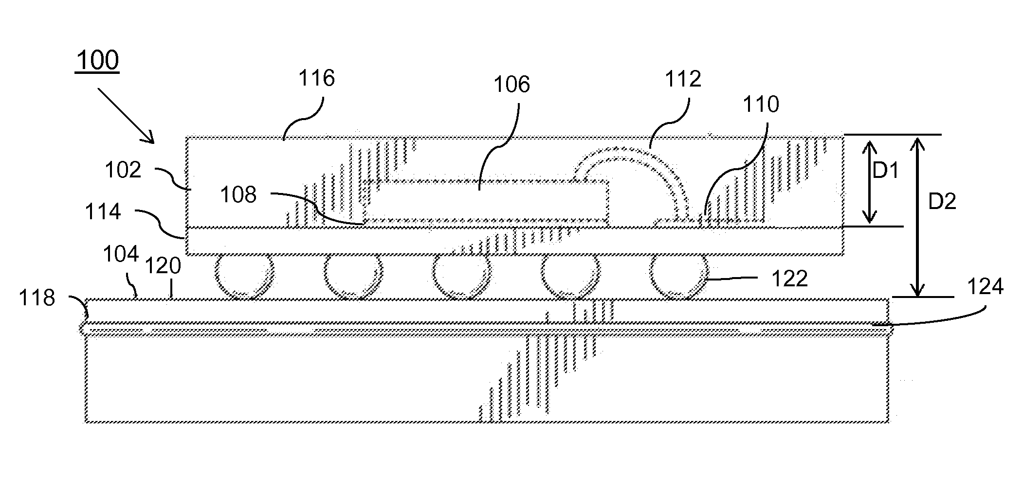
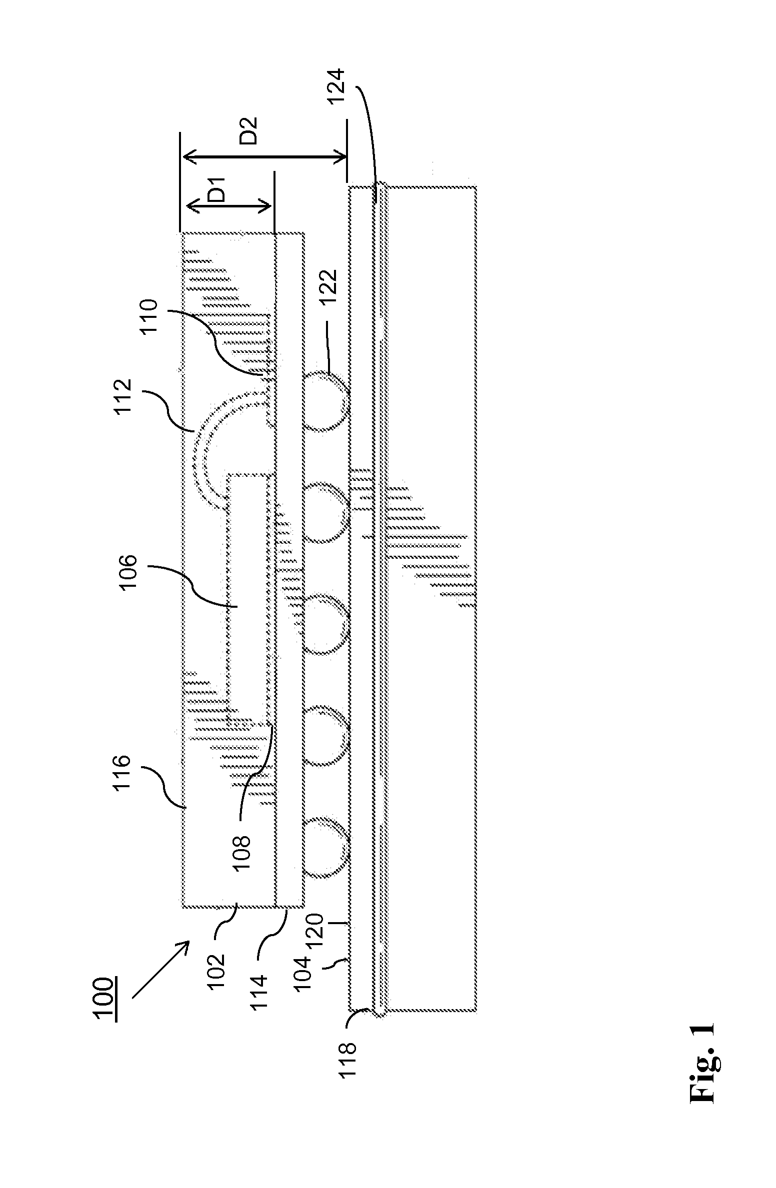
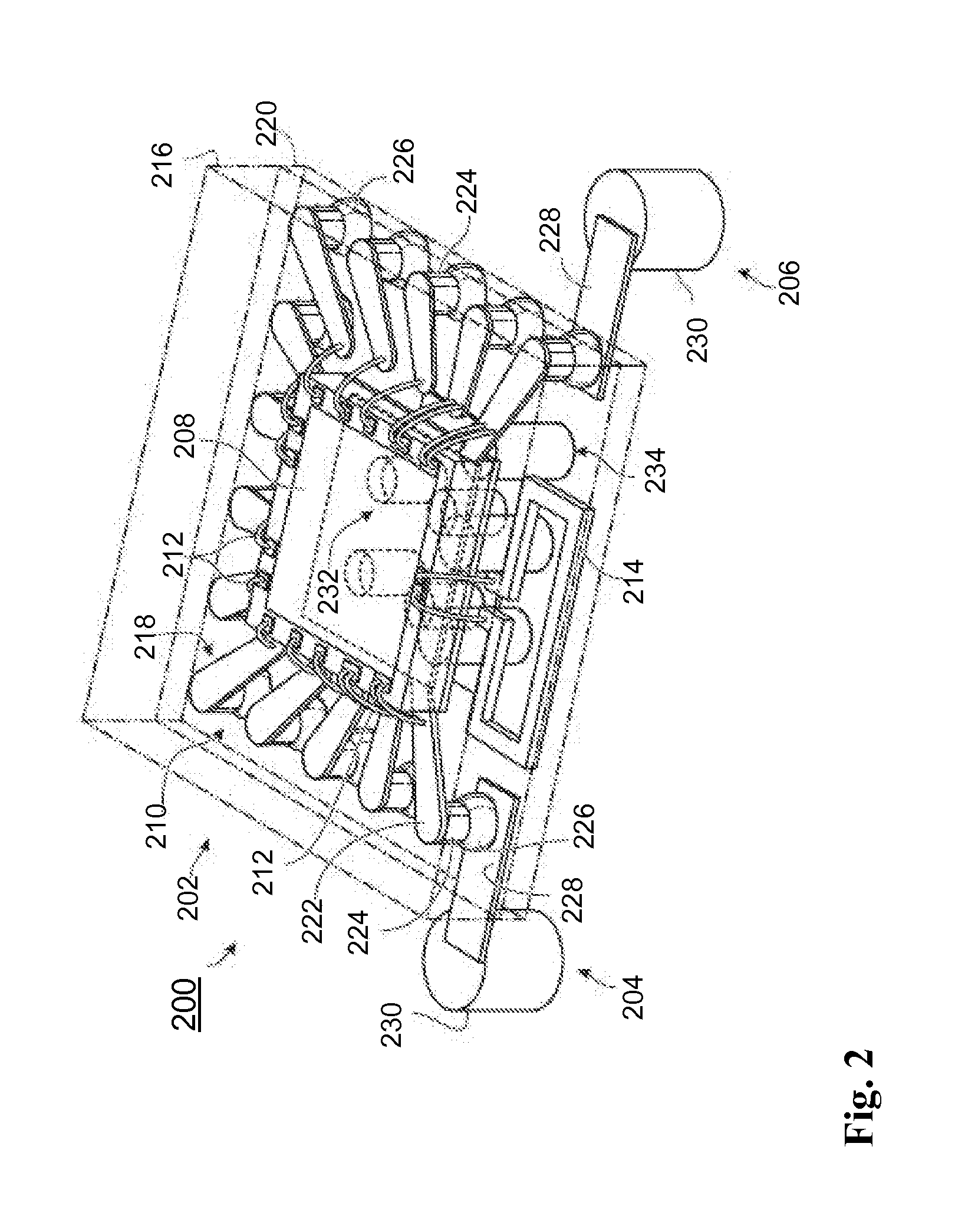
[0021]Before describing this in detail, it should be observed that apparatus components and method steps described relate to electronic devices capable of EHF communication. Accordingly the apparatus components have been represented where appropriate by conventional symbols in the drawings, showing only specific details that are pertinent for an understanding of the present inventions so as not to obscure the disclosure with details that will be readily apparent to those with ordinary skill in the art having the benefit of the description herein.

[0022]While the specification concludes with the claims defining features that are regarded as novel, it is believed that the inventions will be better understood from a consideration of the following description in conjunction with the drawings, in which like reference numerals are carried forward.

[0023]As required, detailed embodiments are disclosed herein; however, it is to be understood that the disclosed embodiments are merely exemplary...


PUM


Abstract

An electronic device may include a PCB having a substantially planar surface and one or more electronic components mounted thereon. A first EHF communication unit may be mounted on the substantially planar surface of the PCB. The first EHF communication unit may include a first planar die containing a first communication circuit, the first die extending along the substantially planar surface of the PCB in a die plane. A first antenna may be operatively connected to the first circuit by interconnecting conductors, the first antenna being configured to at least one of transmit and receive electromagnetic radiation along a plane of the substantially planar surface of the PCB. The first EHF communication unit may have an uppermost surface having a height from the substantially planar surface of the PCB, the first EHF communication unit height being determined by an uppermost surface of the die, the first antenna, and the interconnecting conductors.

Description

CROSS-REFERENCE TO RELATED APPLICATIONS[0001]This application claims the benefit of the U.S. Provisional Patent Application having Ser. No. 61 / 549,378, filed on Oct. 20, 2011 and entitled “Zero Height Connectors”, which is incorporated herein by reference in its entirety for all purposes.TECHNICAL FIELD[0002]The disclosure relates to data transfer using Extremely High Frequency (EHF) communications devices. More particularly, the disclosure relates to wireless data transfer using EHF communications devices.BACKGROUND[0003]Advances in semiconductor manufacturing and circuit design technologies have enabled the development and production of integrated circuits (ICs) with increasingly higher operational frequencies. In turn, electronic products and systems incorporating such integrated circuits are able to provide much greater functionality than previous generations of products. This additional functionality has generally included the processing of increasingly larger amounts of data a...

Claims


Application Information

Patent Timeline
IPC IPC(8): H01Q21/24H01Q1/36
CPCH01L23/66H01L2223/6677H01L2924/15311H01L2224/73265H01L2224/48091H05K1/0239H05K1/0243H05K1/142H05K2201/10098H05K2201/10446H01Q1/36H01Q21/24H04B5/0031H01L23/495H01L23/4951H01L2924/14H01L2924/3011H01L2924/00014H01L2924/00
Inventor MCCORMACK, GARY D.KYLES, IAN A.
Owner MOLEX INC
Why Eureka
Try Eureka