Image capturing device and image capturing method

Inactive Publication Date: 2013-05-02
FUJIFILM CORP
View PDF2 Cites 18 Cited by
  • Summary
  • Abstract
  • Description
  • Claims
  • Application Information

AI Technical Summary

Benefits of technology

[0040]In addition, the present invention provides an image capturing method for enabling stereoscopic pickup used to acquire a stereoscopic image having a first planar image and a second planar image, respectively generated using a first pixel group and a second pixel group, and plane pickup used to acquire a planar image having the first planar image and the second planar image by imaging a same scene using the first pixel group and the second pixel group using a single optical pickup system, an imaging element that has a first pixel group and a second pixel group respectively performing photoelectric conversion on light fluxes passing through different regions of the single optical pickup system, light extinction unit that can

Problems solved by technology

That is, when a high-resolution planar image is picked up, light fluxes from the same subject pass through the different positions of the pupil of the pickup lens 12, thus there

Method used


Image

  • Image capturing device and image capturing method
  • Image capturing device and image capturing method
  • Image capturing device and image capturing method

Examples


first embodiment

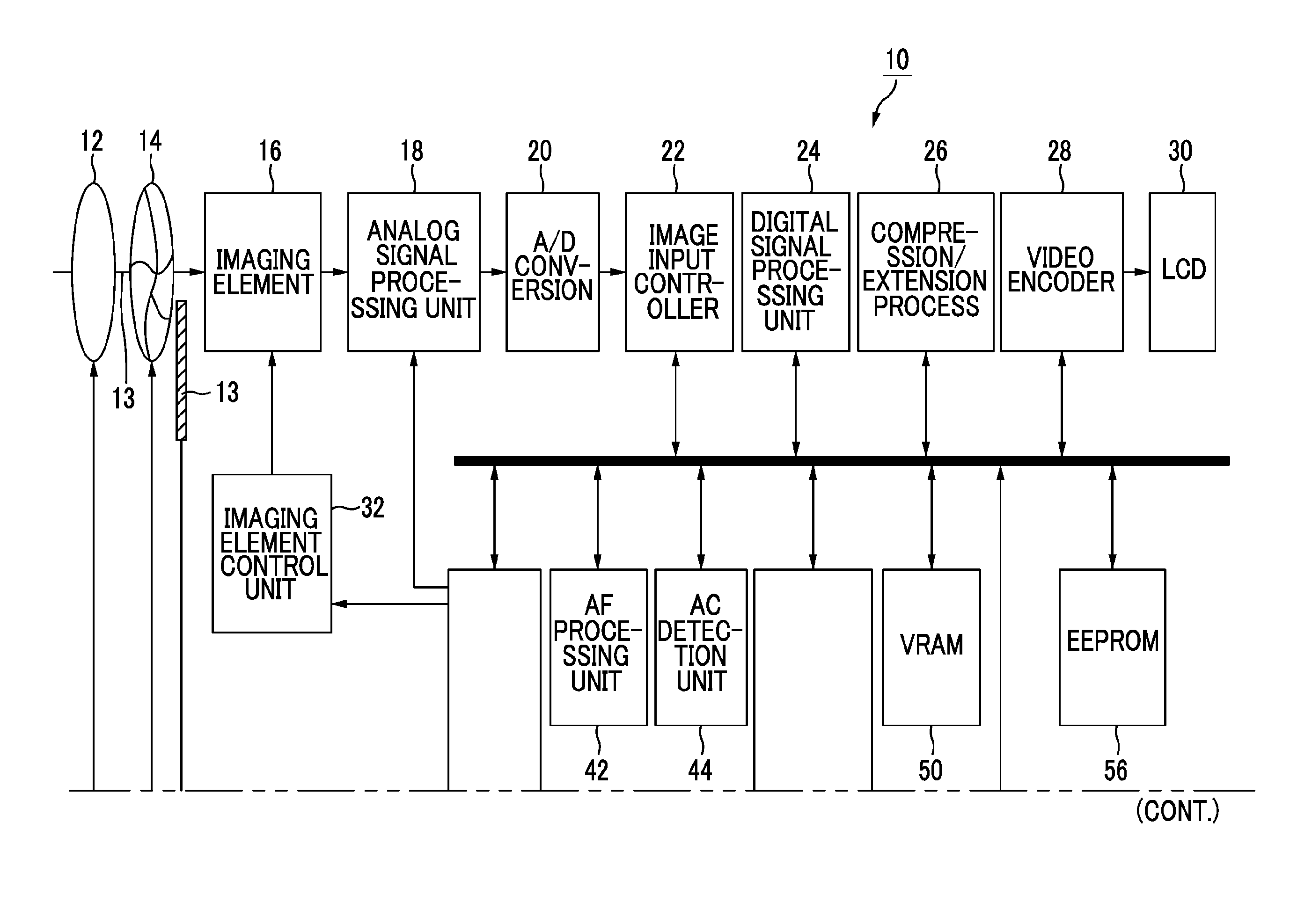
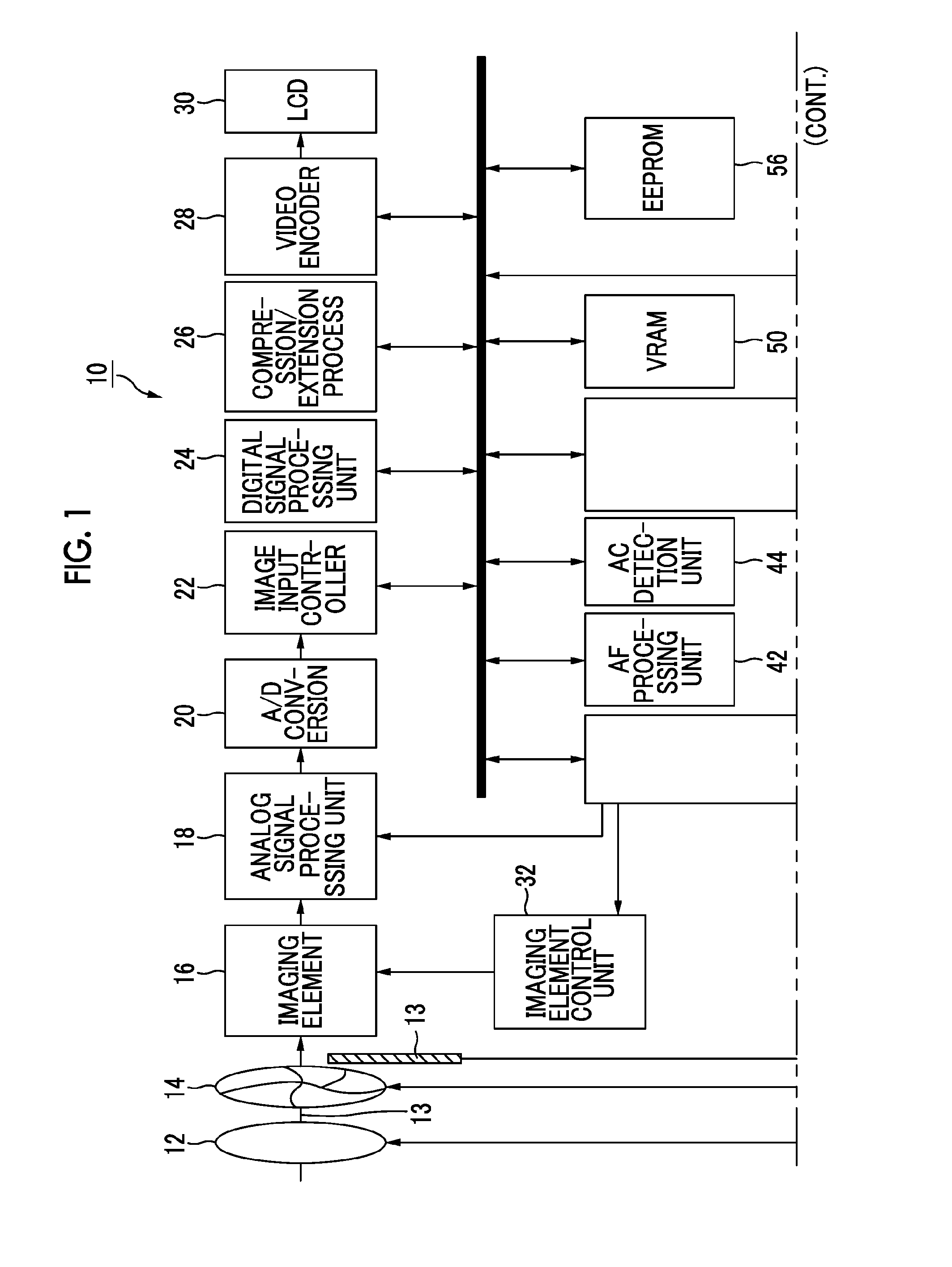
[0110]FIG. 5 is a block diagram illustrating the details of the main section of the image capturing device 10. Meanwhile, in FIG. 5, the same reference numerals are used for the components shown in FIG. 1, and the descriptions of the units which are previously described are omitted below.

[0111]In an image capturing device 10 according to the embodiment, a CPU 40 includes a pickup mode setting control unit 62, an AE control unit 64, an AF control unit 66, a pickup execution control unit 68, and a diaphragm control unit 70.

[0112]The pickup mode setting control unit 62 receives pickup mode setting operation using the operation unit 38, and stores the received pickup mode in the memory 48. The pickup mode includes at least 3D pickup mode and 2D pickup mode. In addition, the 2D pickup mode includes high-resolution 2D pickup mode in which a high-resolution plane (2D) image is generated and low-resolution 2D pickup mode in which a low-resolution plane (2D) image is generated. Hereinafter, ...

second embodiment

[0138]Subsequently, an image capturing device according to a second embodiment will be described with reference to FIG. 5. Meanwhile, hereinafter, units which are different from those in the first embodiment will be mainly described, and the descriptions of the units which are previously described in the first embodiment are omitted.

[0139]In the case of 2D pickup, the diaphragm control unit 70 according to the embodiment controls whether or not to set the ND filter 15 to the insertion state based on the subject distance of a main subject (focused subject) which is acquired using the AF control unit 66. For example, in the case of 2D pickup, when the subject distance of the focused main subject is greater than the threshold Ts (when the main subject is far), the diaphragm 14 is set to the open state (the diaphragm value is the minimum value). When the subject distance of the focused main subject is equal to or less than the threshold Ts (the main subject is close), the diaphragm valu...

third embodiment

[0149]Subsequently, an image capturing device according to a third embodiment will be described with reference to FIG. 8. Meanwhile, hereinafter, units which are shown in FIGS. 5 and 6 and are different from those in the first embodiment will be mainly described, and the descriptions of the units which are previously described in the first embodiment are omitted.

[0150]FIG. 8 is a block diagram illustrating the main section of the image capturing device 10 according to the third embodiment. Meanwhile, in FIG. 7, the same reference numerals are used for the components which are shown in FIGS. 1 and 5.

[0151]The pickup lens 12 includes a zoom lens, and the focal distance acquisition unit 72 acquires the focal distance of the pickup lens 12.

[0152]In the case of 2D pickup, the diaphragm control unit 70 according to the embodiment controls whether or not to set the ND filter 15 to the insertion state based on the focal distance of the pickup lens 12 which is acquired using the focal distan...


PUM


Abstract

The quality of a planar image is improved while maintaining the parallax of a stereoscopic image. An image capturing device includes an imaging element that performs photoelectric conversion on respective light fluxes passing through different regions of a single pickup lens. The image capturing device includes a neutral density filter an AE control unit that acquires subject brightness, and a diaphragm control unit that, in a case of the stereoscopic pickup, controls whether or not to reduce the amount of light which reaches the imaging element using the neutral density filter based on the subject brightness, and that, in a case of the plane pickup, causes a diaphragm value of the diaphragm to be greater than a diaphragm value in the case of the stereoscopic pickup while setting the light extinction filter to a non-insertion state.

Description

BACKGROUND OF THE INVENTION[0001]1. Field of the Invention[0002]The present invention relates to an image capturing device and an image capturing method which can generate a stereoscopic image including planar images viewed from multiple viewpoints using a single optical pickup system.[0003]2. Description of the Related Art[0004]In the related art, an image capturing device is known which can generate a stereoscopic image including planar images viewed from multiple viewpoints using a single optical pickup system.[0005]JP2009-527007T discloses a configuration in which a single optical pickup system is provided and pupil division is performed by rotating a diaphragm, thereby generating a stereoscopic image.[0006]JP2009-168995A discloses a configuration in which polarizing elements are provided and light is received using an imaging element for each light path, thereby acquiring phase information using a single optical pickup system.[0007]JP1998-42314A (JP-H10-42314A) discloses an ima...

Claims


Application Information

Patent Timeline
IPC IPC(8): H04N13/02
CPCG03B7/08G03B11/00H04N13/0217H04N5/23212H04N5/238G03B35/08H04N23/672H04N23/673H04N23/75H04N25/134H04N13/211H04N13/218G02B27/0988
Inventor ENDO, HIROSHI
Owner FUJIFILM CORP
Why Eureka
Try Eureka