Scroll compressor

a compressor and compressor technology, applied in the direction of machines/engines, rotary/oscillating piston pump components, liquid fuel engines, etc., can solve the problems of stability and reliability, poor stability of refrigerant having a small global warming potential, and problems such as the use of hfc refrigerant becomes a problem, so as to promote the decomposition of refrigerant and reduce the effect of ozone depletion and small global warming potential

Active Publication Date: 2013-05-02
PANASONIC INTELLECTUAL PROPERTY MANAGEMENT CO LTD
View PDF8 Cites 16 Cited by
  • Summary
  • Abstract
  • Description
  • Claims
  • Application Information

AI Technical Summary

Benefits of technology

[0012]The scroll compressor according to the present invention employs therein a refrigerant having a small global warming potential and a small ozone depletion potential and can restrain a temperature increase of the ref...

Problems solved by technology

Conventional refrigerating appliances generally employ an HFC (hydrofluorocarbon) refrigerant having a zero-ozone depletion potential as a refrigerant, but in recent years the use of the HFC refrigerant becomes a problem because it has a very large global warming potential.
However, the refrigerant ...

Method used


Image

  • Scroll compressor
  • Scroll compressor
  • Scroll compressor

Examples


embodiment 1

[0032]In the present invention, a single-component refrigerant mainly comprising hydrofiuoroolefin having a carbon-carbon double bond or a mixture refrigerant containing this refrigerant is used as a refrigerant

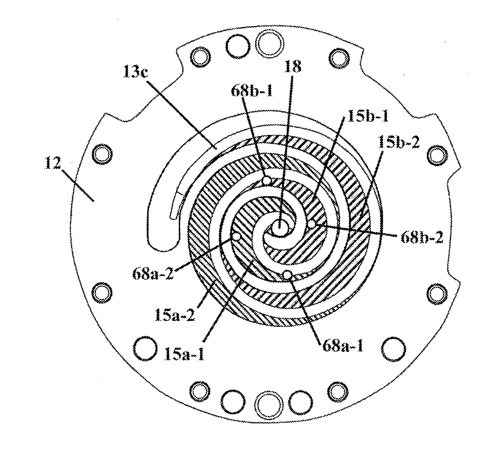
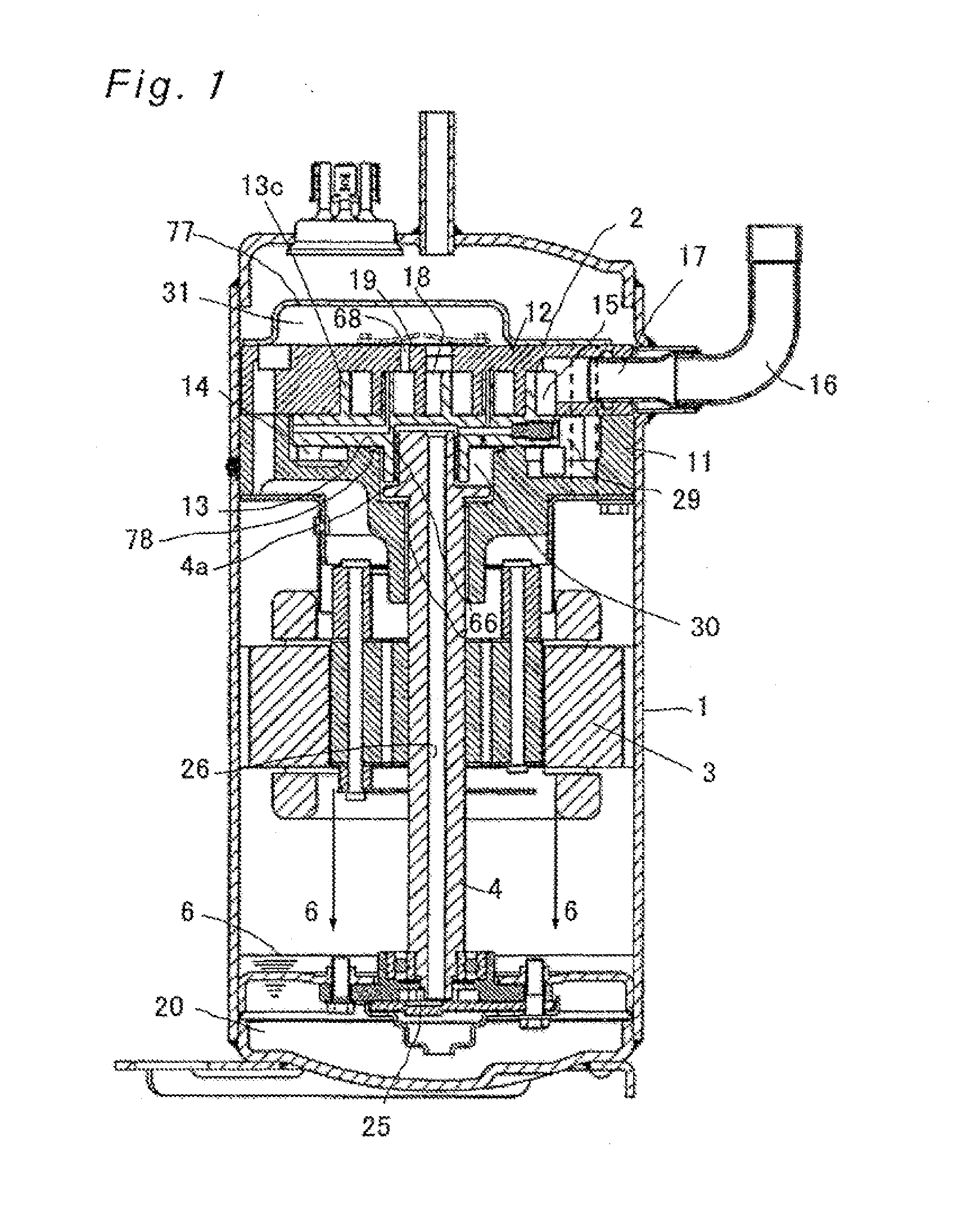
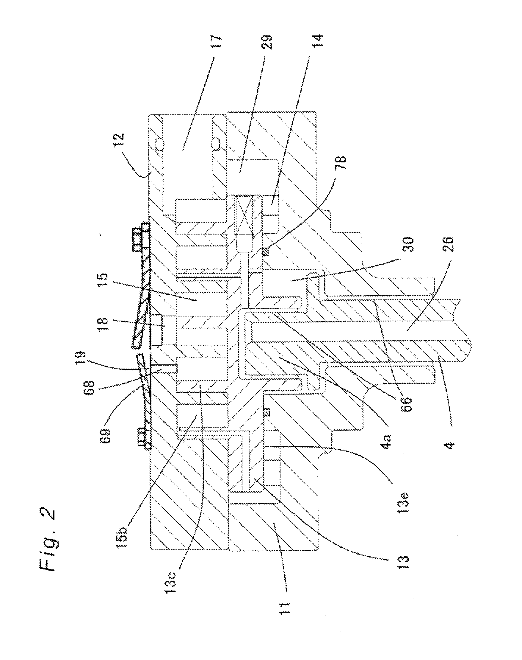
[0033]FIG. 1 is a vertical sectional view of a scroll compressor according to a first embodiment of the present invention, FIG. 2 is an enlarged sectional. view of an essential portion of a compression mechanism mounted in the scroll compressor of FIG. 1, and FIG. 3 is a top plan view of the compression mechanism. Operation and function of the scroll compressor are explained hereinafter.

[0034]As shown in FIG. 1, the scroll compressor according to the first embodiment of the present invention includes a dosed container 1, in which a compression mechanism 2, an electric motor 3 and an oil sump 20 are accommodated. Details of the compression mechanism 2 are explained with reference to FIG. 2. The closed container 1 accommodates a main bearing 11 secured thereto by welding or shr...

embodiment 2

[0041]FIG. 5 is a top plan view of a compression mechanism mounted in a scroll compressor according to a second embodiment of the present invention. Because the configuration other than bypass holes 68ab is the same as that in the first embodiment, the same component parts as those shown in FIG. 3 are designated by the same signs in FIG. 5, only the bypass holes 68ab are explained and explanation of the rest is omitted.

[0042]As shown in FIG. 5, in the scroll compressor according to the second embodiment, the bypass holes 68ab are provided at positions where they communicate with the first compression chamber 15a and the second compression chamber 15b, but any one of them does not simultaneously open into the first compression chamber 15a and the second compression chamber 15b with an orbital movement of the orbiting scroll 13. To this end, the bypass holes 68ab have a diameter smaller than a thickness of an orbiting scroll wrap 13c. At a crank angle shown in FIG. 5, the bypass hole ...


PUM


Abstract

A scroll compressor employs therein a refrigerant having a small global warming potential and a small ozone depletion potential and mainly comprising hydrofluoroolefin having a carbon-carbon double bond. A stationary scroll has and end plate and a discharge port defined in the end plate at a central portion thereof so as to open into a discharge chamber. The stationary scroll also has a bypass hole defined in the end plate to allow a plurality of compression chambers to communicate with the discharge chamber before the compression chambers communicate with the discharge port. A check valve is provided on the bypass hole to allow the refrigerant to flow from the compression chambers to the discharge chamber. This construction can restrain a baneful influence on the global environment, reduce a temperature increase caused by excessive compression, and restrain decomposition of the refrigerant even in long-term use.

Description

TECHNICAL FIELD[0001]The present invention relates to a scroll compressor that can be incorporated into refrigerating cycles such as, for example, room-air conditioners, car-air conditioners, refrigerators or other air conditioners in which a refrigerant containing no chlorine atoms, having a small global warming potential, and mainly comprising hydrofluoroolefin having a carbon-carbon double bond is employed as a refrigerant.BACKGROUND ART[0002]Conventional refrigerating appliances generally employ an HFC (hydrofluorocarbon) refrigerant having a zero-ozone depletion potential as a refrigerant, but in recent years the use of the HFC refrigerant becomes a problem because it has a very large global warming potential. In view of this, a compressor for use with a refrigerant having a small ozone depletion potential and a small global warming potential has been developed. However, the refrigerant having a small global warming potential generally shows poor stability and has a problem in ...

Claims


Application Information

Patent Timeline
IPC IPC(8): F04C28/26F04C18/02
CPCF04C18/0215F04C28/26F04C29/128F04C18/0261F04C2210/263F04C23/008F04C2210/26
Inventor NAKAI, HIROAKIYOSHIDA, HIROFUMIKARINO, TSUYOSHIOHNO, RYUICHIOYAGI, SHINGOIIDA, NOBORU
Owner PANASONIC INTELLECTUAL PROPERTY MANAGEMENT CO LTD
Why Eureka
Try Eureka