
Connector retaining device

Inactive Publication Date: 2013-05-02
NUETEQ TECH +1
View PDF10 Cites 3 Cited by
  • Summary
  • Abstract
  • Description
  • Claims
  • Application Information

AI Technical Summary

Benefits of technology

The patent text describes a retaining device that strengthens the connection between a connector and a multimedia device, preventing the connector from detaching and affecting signal transmission. The device can be used with different connector specifications, reducing disturbances for users. It is also easier to manufacture, aesthetically appealing, and has a longer service life compared to conventional fastening devices.

Problems solved by technology

Hence, preventing the connector to detach from the multimedia device, due to loosening, that may affect the signal transmission.

Method used


Image

  • Connector retaining device
  • Connector retaining device
  • Connector retaining device

Examples


first embodiment

The First Embodiment

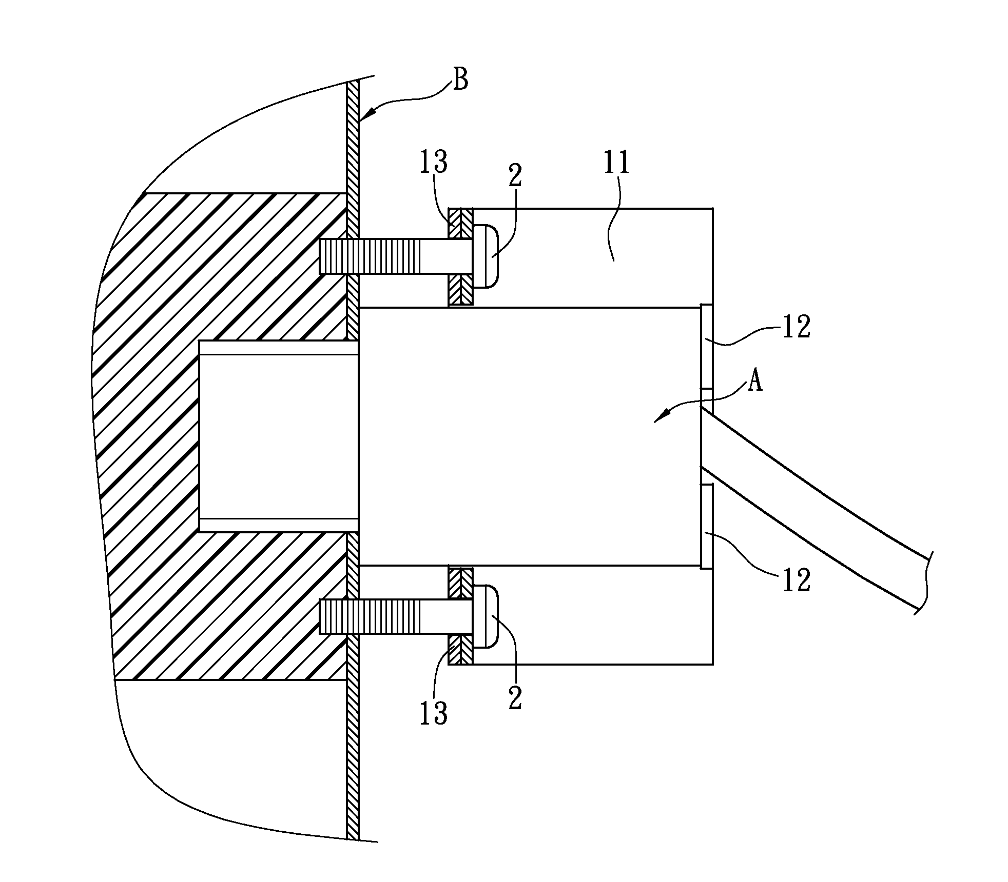
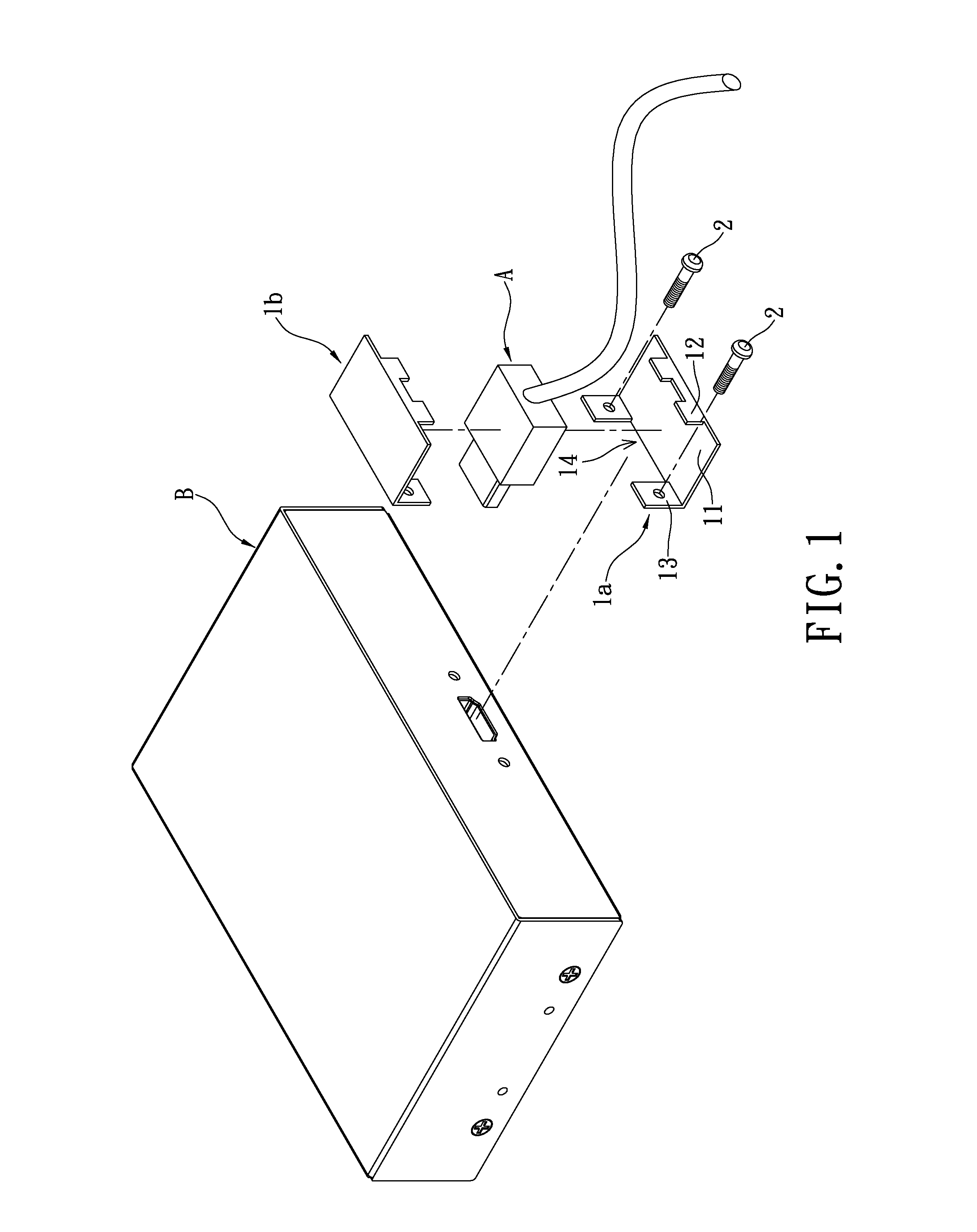
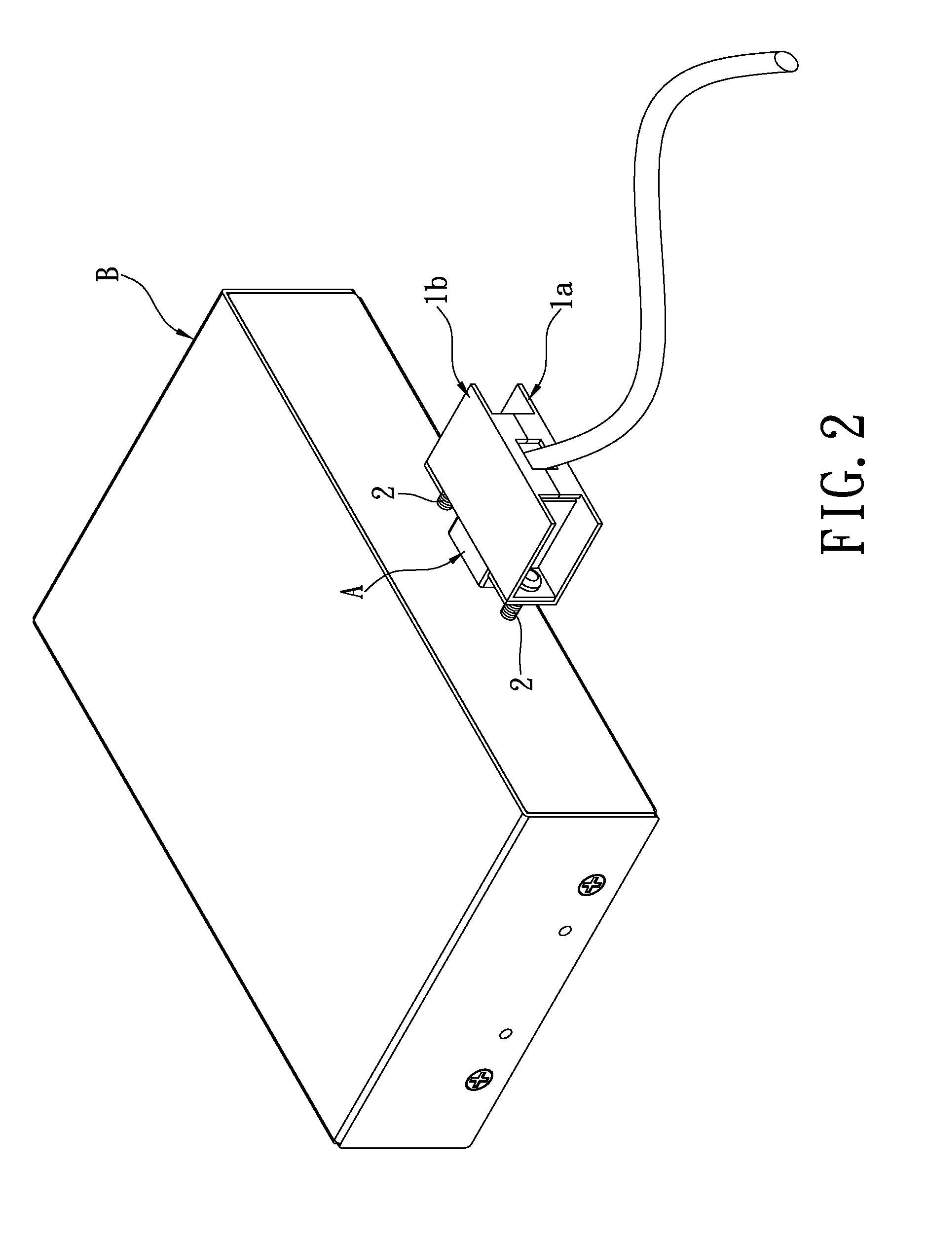
[0018]With reference to FIGS. 1-3, the instant disclosure provides a retaining device which includes two engaging members 2 and two housings 1a and 1b. Each of the housings 1a and 1b includes a plate portion 11, an abutting portion 12 and a pair of fixing portions 13. By the orientation of the figures, the abutting portion 12 is arranged on a back portion of the plate portion 11, where the fixing portions 13 are arranged on a front portion of the plate portion 11, and the plate portion 11 and the fixing portions 13 cooperatively define a notch 14 having a cross sectional dimension greater than that of the high definition multimedia interface connector. When the connector A is disposed on the plate portion 11 of the housing 1a, the abutting portion 12 of the housing 1a will abut against the back surface of the connector A, while the connector A has a protrusion (not labeled) arranged on the front portion thereof, will project from the notch 14 of the housing 1a to...

second embodiment

The Second Embodiment

[0020]With reference to FIG. 4, the difference between the instant embodiment and the preceding embodiment is that a foldable portion 15 is formed between for connecting the two housings 1a and 1b in the instant embodiment.

[0021]When the connector A (shown in FIG. 2) is disposed in the housing 1a, the other housing 1b can be folded to encase the connector A through bending the foldable portion 15. After the connector A is encased by the two housing 1a and 1b, the fixing portions 13 of the two housings 1a and 1b will be adjacently arranged. Next, the housings 1a and 1b will be screwed to the multimedia device B (shown in FIG. 2) through the engaging member 2, such that the connector A, the housings 1a and 1b, and the multimedia device B will be mutually stabilized to strengthen the connection for the connector A.

third embodiment

The Third Embodiment

[0022]With reference to FIG. 5, the difference between the instant embodiment and the first embodiment is that only one housing 1c is utilized to load the connector A (shown in FIG. 2).

[0023]For the housing 1c of the instant embodiment, other than the abutting portion 12 which abuts against one end of the connector A, the abutting portion 12 further has a clutching portion 121 which engages the cables connected at the end of the connector A. Therefore, the connector A will be well-engaged when loaded on the housing 1c. Furthermore, the protrusion (not labeled) of the connector A will be inserted into the multimedia device B (shown in FIG. 2). Thus, the housing 1c will be screwed to the multimedia device B through the fixing portion 13 thereof, such that the connector A, the housings 1c, and the multimedia device B will be mutually stabilized to strengthen the connection for the connector A.


PUM


Abstract

A cable connector retaining device sleevedly adaptable over a high definition multimedia interface connector includes at least one engaging member and a housing. The housing includes a plate portion, an abutting portion and a fixing portion. The abutting portion is arranged on a back portion of the plate portion for establishing pressing contact against the back portion of the connector. The fixing portion receptive of the engaging member is arranged on a front portion of the plate portion. The engaging member is connectable to the multimedia device through the fixing portion. The plate portion and the fixing portion cooperatively define a notch having a cross sectional dimension greater than that of the high definition multimedia interface connector. The retaining device is adaptable on connectors of different specifications, hence, bringing fewer disturbances to users in selection of the connectors.

Description

BACKGROUND OF THE INSTANT DISCLOSURE[0001]1. Field of the Instant Disclosure[0002]The instant disclosure relates to a retaining device for cable connectors; in particular, to a universal retaining device adaptable for retaining high definition multimedia interface (HDMI) connectors of different sizes.[0003]2. Description of Related Art[0004]The development of high definition televisions has driven the production of the peripheral accessories such as TV decoders, the DVD players, or the storage device for high definition multimedia clips. However, such products often rely on cables for data transmission (such as DVI cable). Furthermore, insecure structural connection between the cable connector and the multimedia device may affect the transmission efficiency and thus the output quality. For instance, the connector may be accidentally loosened or detached from the multimedia device during room cleaning. Furthermore, along with the increasing popularity of wall mounted TV, many multime...

Claims


Application Information

Patent Timeline
IPC IPC(8): H01R13/622
CPCH01R13/6395
Inventor CHANG, HUI-CHIH
Owner NUETEQ TECH
Learn More