
Multi-Network Multi-Plane Structure Short Message Centre System and Implementation Method Thereof

a message center and multi-plane technology, applied in the field of communication, can solve the problems of service breakdown or affect, high probability of faults, and inconvenient networking, and achieve the effects of convenient and flexible implementation, strong integration, and simplified system structur

Inactive Publication Date: 2013-05-02
ZTE CORP
View PDF4 Cites 16 Cited by
  • Summary
  • Abstract
  • Description
  • Claims
  • Application Information

AI Technical Summary

Benefits of technology

The present invention provides a short message center system with multi-network multi-plane structure that can ensure continuous service even when certain modules or all the modules of a real short message office fail. This system simplifies the system structure, simplifies the load-balancing policy, and brings more convenience and flexibility in aspects such as link management and operation and maintenance. Overall, this system has better security and stability, and ensures strong integration, easy expansion and management.

Problems solved by technology

Firstly, when one short message office is faulted, all the services can only be handed over to the other office, and if the other office is also faulted or overloaded, the service will break down or be affected.
Secondly, the double-network double-plane technology requires short message office joining therein to be pairwise inter-networked. To enhance the security of the short message center, multiple short message offices are formed into a multi-network multi-plane structure, however, this networking way is very inconvenient. Because, at first, each office should record the information of all the other office, and when one office is added, deleted or modified, the data of all the other office needs to be reconfigured; next, given that there are N office in network, N*(N−1) / 2 links need to be maintained, and the more the office are, the more complex the links are, and the more difficult the management for the links is, thus the higher the probability of faults occurring is.
Thirdly, there lacks the function of monitoring and management for the traffic load of whole system. Each node manages the traffic relevant to itself in a distributed way, without one node being able to monitor the traffic of whole network, incapable of configuring and performing a flexible load-balancing policy.
Firstly, its architecture is much complicated, one cluster crunode server being also needed to be built for every short message office aside from the cluster dispatch center being needed to be built.
Secondly, aside from supporting the star structure centering around the cluster dispatch center, the cluster system also supports the way of cluster crunode servers connecting to one another directly, and the disadvantages of this way are similar to the double-network double-plane structure.
Thirdly, the cluster dispatch center has only one single service processing module, without being divided into a signaling processing module, a service processing module and a short message peer to peer protocol agent (SMPP AGENT) module, only providing uniform message interface. Thus, the cluster crunode server needs to convert messages received from these three modules using different protocols into one uniform message format when exchanging messages with the cluster dispatch center, and also needs to convert protocols for messages when sending messages to these three modules. These conversions increase the burden of hardware and the time of processing messages.
Fourthly, the operation status and load condition of the short message center is reported regularly to the cluster dispatch center by cluster crunode, and the cluster dispatch center then invokes a load-balancing policy to shunt the load, and the real time property of load reporting is not strong; meanwhile, the accuracy of load reporting is also not good due to different operating systems and the processing mechanism of the short message center and the like factors.

Method used


Image

  • Multi-Network Multi-Plane Structure Short Message Centre System and Implementation Method Thereof
  • Multi-Network Multi-Plane Structure Short Message Centre System and Implementation Method Thereof
  • Multi-Network Multi-Plane Structure Short Message Centre System and Implementation Method Thereof

Examples


Embodiment Construction

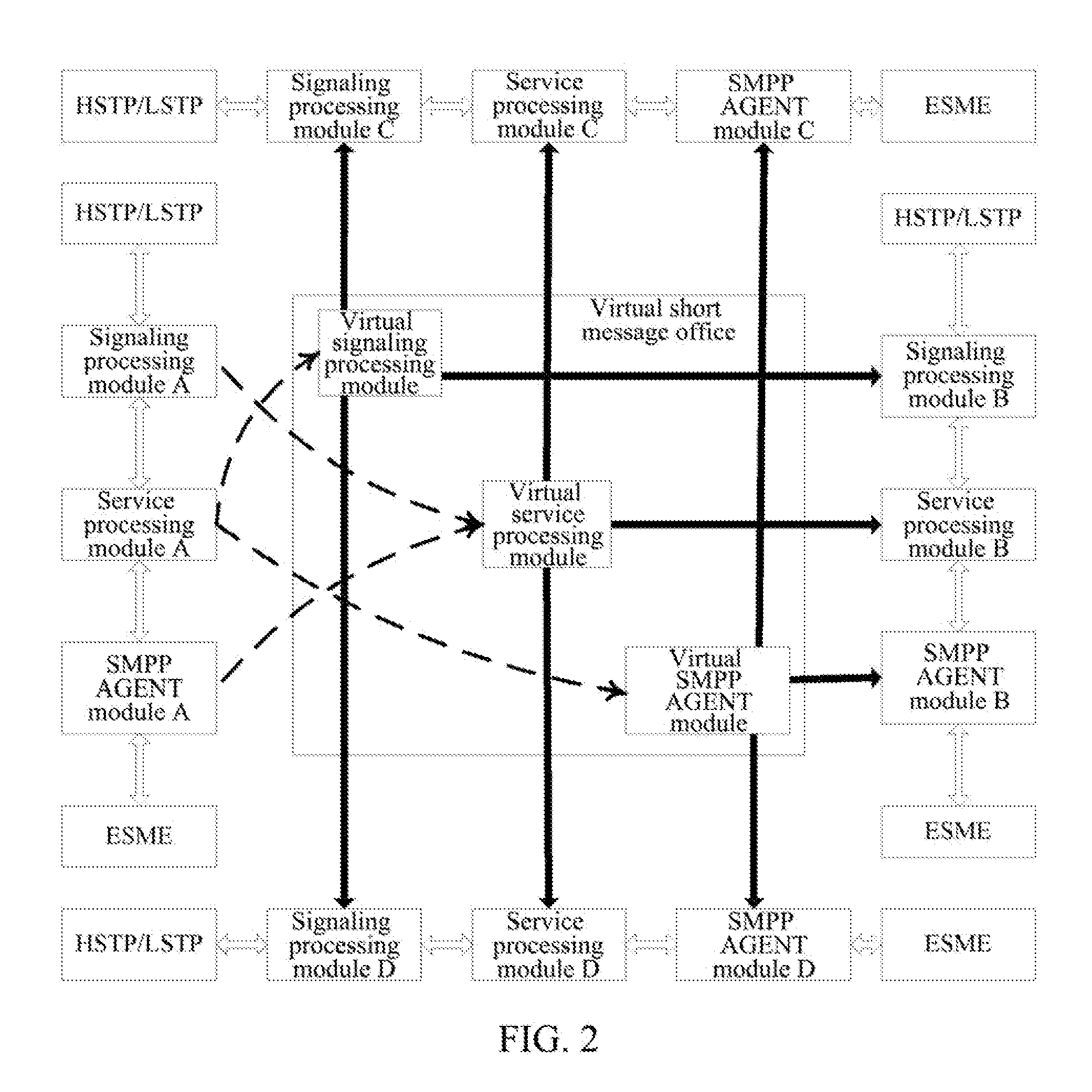
[0047]The short message center system with multi-network multi-plane structure and implementation method thereof of the present invention are illustrated in conjunction with the following drawings.

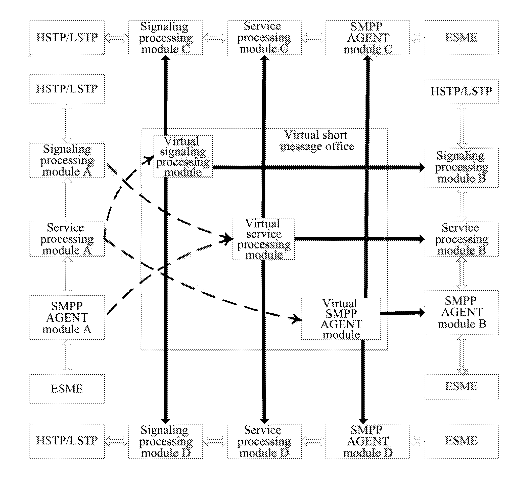
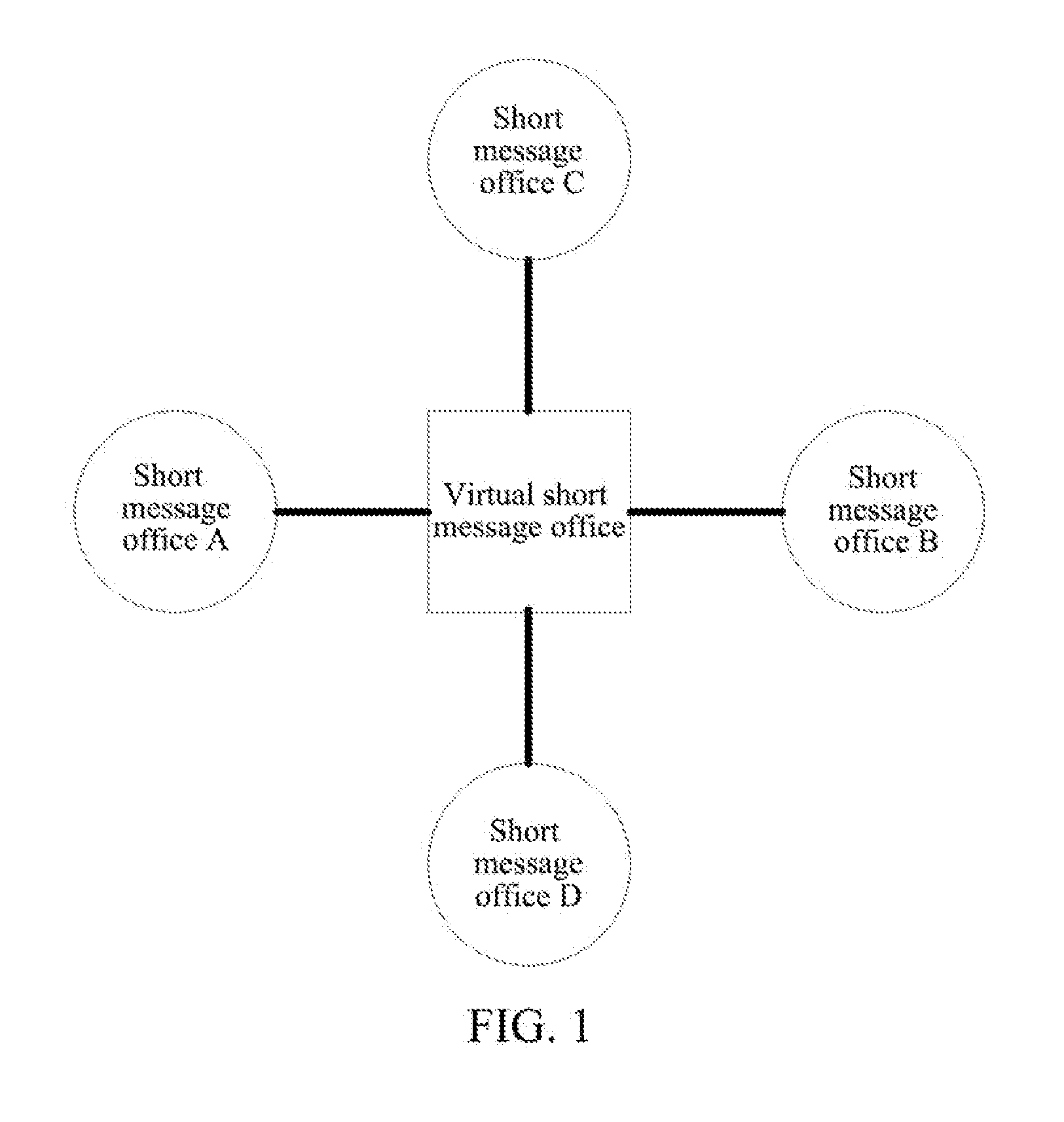
[0048]Please refer to FIG. 1, it illustrates the structure of a short message center system with multi-network multi-plane structure of the present invention.

[0049]The short message center system with multi-network multi-plane structure of the present invention includes a virtual short message office, short message office A, short message office B, short message office C and short message office D. Relative to the virtual short message office, short message office A, short message office B, short message office C and short message office D may be called real short message offices.

[0050]Short message office A, short message office B, short message office C and short message office D are connected with the virtual short message office respectively, thereby a star network centering around the...


PUM


Abstract

A short message center system and an implementation method thereof are disclosed in the present invention, to implement the short message center system with multi-network multi-plane structure. The short message center system includes a virtual short message office and at least two short message offices. Wherein the short message office includes a signaling processing module, a service processing module and SMPP AGENT module, the virtual short message office includes a forwarding module and a returning module, the forwarding module is used to, when the module of short message office is faulted, forward a message to be processed by the faulted module to a corresponding module in another short message office to be processed, the returning module is used to return a processing result to the short message office with faulted module.

Description

TECHNICAL FIELD[0001]The present invention relates to communication field, and especially, to a short message center system with multi-network multi-plane structure and an implementation method thereof.BACKGROUND OF THE RELATED ART[0002]The short message service is an important service among mobile communication services, the income thereof accounting for a growing percentage of total operator income. Hence, the operating security and stability of the short message center, the core of what provides the service, have also become a focus of increasing attention of operators and device manufacturers.[0003]At present, there are mainly two technical schemes used by short message service, which are respectively: double-network double-plane and cluster.[0004]Wherein, in the double-network double-plane scheme, two or more short message offices are connected to network by the way of pairwise interconnecting, and once one short message office is faulted, the other short message office may tak...

Claims


Application Information

Patent Timeline
Patent Type & Authority Applications(United States)
IPC IPC(8): H04L12/58H04L69/40H04L45/28
CPCH04L12/5895H04L51/38H04W4/14H04W24/04H04W88/184H04L67/1034H04L51/06H04L43/0817H04L41/0816H04L45/28H04L69/40H04L41/046H04L43/0876H04L41/0668H04L51/23H04L51/58H04L41/40H04L43/20H04L41/0894H04L41/0893
Inventor YANG, YIKUNCHEN, ZHENGGUANGNIE, RONGCHU
Owner ZTE CORP
Learn More