Tubular Composite Strut Having Internal Stiffening and Method for Making the Same

a composite strut and tubular technology, applied in the field of composite columnar structures, can solve the problems of labor-intensive and time-consuming fabrication of these types of composite struts, and achieve the effects of optimizing the structural strength-to-weight ratio of struts, optimizing strut performance, and tailoring skin thickness

Active Publication Date: 2013-05-09
THE BOEING CO
View PDF7 Cites 32 Cited by
  • Summary
  • Abstract
  • Description
  • Claims
  • Application Information

AI Technical Summary

Benefits of technology

[0007]The disclosed embodiments provide a tubular composite strut and related fabrication method that optimize of the structural strength-to-ratio of the strut through the use of a tailored cross sectional tube configuration that employs internal stiffeners co-cured with the tube body, as well as the ability to tailor skin thickness. The strut is fabricated using an internal mandrel that allows layup of the internal stiffeners engineered to result in an idealized moment of inertia value and maximize strut performance. The internal mandrel allows use of an automatic fiber placement machine to layup plies of the tube body and the stiffeners, which may reduce the need for an autoclave cure cycle to achieve a desired compaction. The tube body is bonded to the end fittings using a step joint with a single side bond. The internal stiffeners may be positioned and engineered to resist bending forces depending on the plane of loading from attachment, thereby allowing a reduction of the thickness of the tube body wall.
[0009]According to another embodiment, a strut is provided for transferring loads in compression or tension. The strut comprises an elongate tubular body having a wall formed of multiple laminated composite plies, and end fittings adapted to attach the tubular body to a structure using a pin. The strut further comprises a single shear bonded joint between each of the fittings and the tubular body, and composite stiffeners within the tubular body attached to the wall for stiffening the body. Each of the end fittings transfers loads to the tubular body about the longitudinal axis of the corresponding pin. The composite stiffeners include at least a first pair of opposing stiffeners aligned along an axis substantially perpendicular to the pin axes.

Problems solved by technology

Fabrication of these types of composite struts is both labor intensive and time consuming because of the need for precise hand layup of plies, as well as the need for two autoclave cure cycles for separately curing the inner and outer plies of the joint.

Method used


Image

  • Tubular Composite Strut Having Internal Stiffening and Method for Making the Same
  • Tubular Composite Strut Having Internal Stiffening and Method for Making the Same
  • Tubular Composite Strut Having Internal Stiffening and Method for Making the Same

Examples


Embodiment Construction

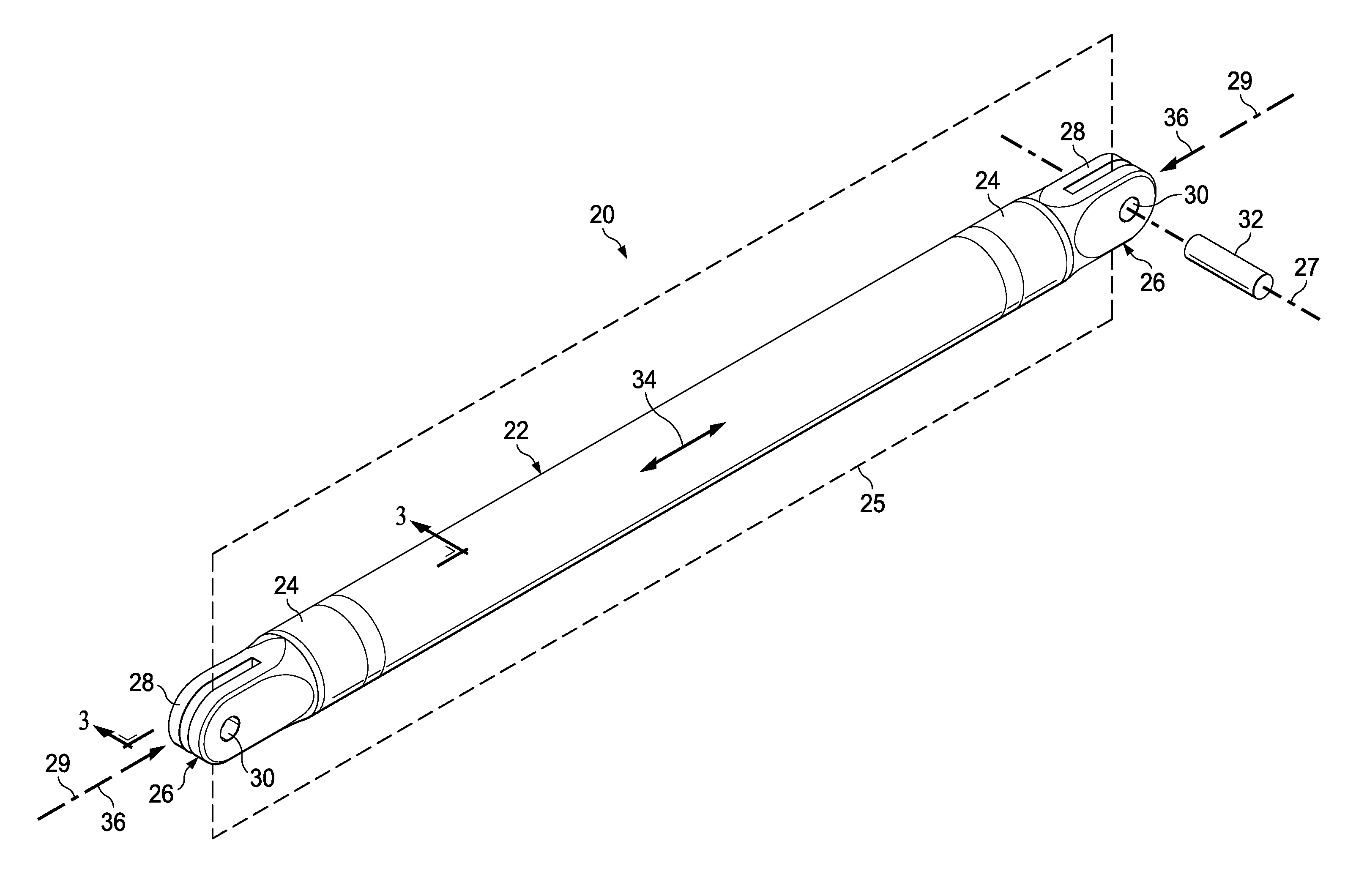
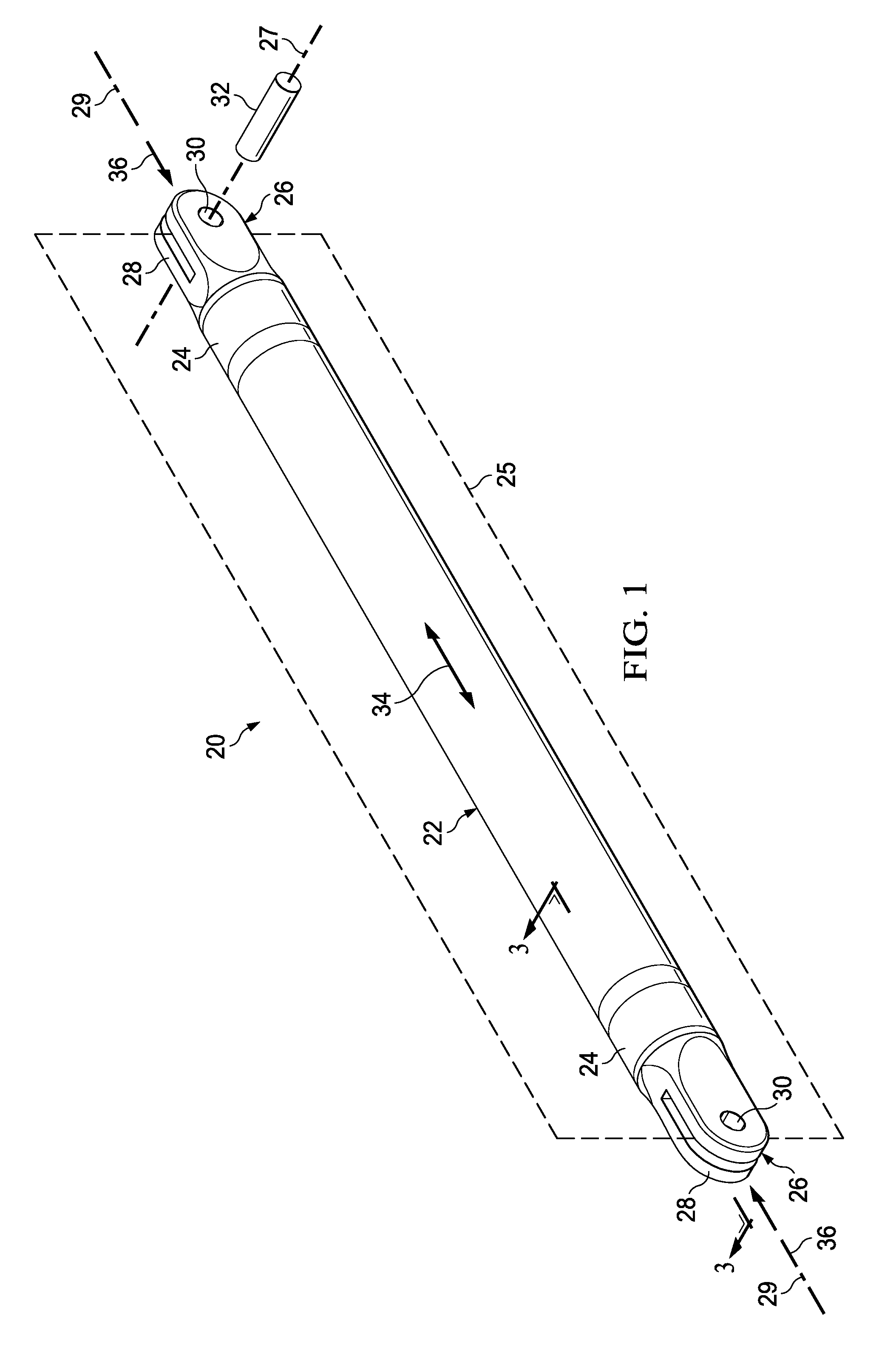
[0033]Referring first to FIG. 1, a columnar structural member in the form of an elongate strut 20 comprises a generally cylindrical tube 22 and a pair of end fittings 24 bonded on opposite ends of the tube 22. The tube 22 may comprise, but is not limited to a composite material, such as multiple laminated plies of a fiber reinforced polymer resin, including but not limited to carbon fiber reinforced epoxy. In the illustrated example, the cross sectional shape of the tube body 22 is substantially round, however other cross sectional shapes are possible such as, without limitation, square, triangular, hexagonal and pentagonal shapes.

[0034]Each of the end fittings 24 may be, but is not limited to a metal such as aluminum or titanium, or a composite. The end fittings 24 may be fabricated by casting, machining or other common manufacturing techniques. Where the end fittings 24 are formed of composite materials, they may include metallic inserts and / or metallic bushings (not shown). Each ...


PUM

PropertyMeasurementUnit
cross sectional shapeaaaaaaaaaa
tensionaaaaaaaaaa
lengthaaaaaaaaaa

Abstract

A strut comprises a substantially hollow composite tube. A fitting on each end of the tube adapts the strut for attachment to a structure. The tube is stiffened by at least one pair of opposing stiffeners.

Description

BACKGROUND INFORMATION[0001]1. Field[0002]The present disclosure generally relates to composite columnar structures, and deals more particularly with a composite tubular strut internally stiffened to maximize the strut's strength-to-weight ratio.[0003]2. Background[0004]Columnar structures formed of composites are used in a variety of applications because of their favorable strength to weight ratio. For example, composite tubular struts may be used in the aerospace industry as a support or brace for transferring loads in either direction along the longitudinal axis of the strut, thus placing the strut in either compression or tension. Fittings on the ends of the strut provide additional strength at the points of attachment of the strut to a structure.[0005]Composite struts are known in which the end fittings, often fabricated from metal, are attached to a tubular composite body by bonds rather than by fasteners. The tubular bodies have a substantially constant cross section and a re...

Claims


Application Information

Patent Timeline
Patent Type & Authority Applications(United States)
IPC IPC(8): F16L9/14B29C53/56B29C63/10
CPCB29L2031/748B29C70/38B29C70/86Y10T74/2142B29C53/587F16C7/026B29C53/822B29C53/585B29C37/0085B29L2031/06Y02T50/40
Inventor STEWART, SAMUEL RAY
Owner THE BOEING CO
Why Eureka
Try Eureka