Light-weight and sound-damped brake rotor and method of manufacturing the same

a technology of sound-damping brake rotor and manufacturing method, which is applied in the direction of manufacturing tools, brake discs, mechanical equipment, etc., can solve the problems of changing functionality or capability, increasing the manufacturing complexity reducing the service life of the brake rotor, so as to maintenance, and reduce the cost of manufacturing

Inactive Publication Date: 2013-05-09
GM GLOBAL TECH OPERATIONS LLC
View PDF9 Cites 25 Cited by
  • Summary
  • Abstract
  • Description
  • Claims
  • Application Information

AI Technical Summary

Benefits of technology

[0007]A vibration damping element that damps vibration propagation through the brake rotor during a braking event is located within the rotor cheek underneath the at least one braking surface. The vibration damping element facilitates a physically distinct, non-bonded, surface-to-surface interface where relative frictional contacting movement can occur when the brake pad is applied against the braking surface. Such frictional interactions convert mechanical vibratory energy into dissipating thermal energy and ultimately weaken the proliferation of vibrations and their ability to sustain a disruptive, audible noise. Some examples of the vibration damping element are (1) a friction-enhancing coating located between a peripheral radial segment of the flange of the rotor hat and an underside of the rotor cheek and (2) a band which is independent from both the rotor hat and the rotor cheek. The band is preferably annular in shape and confined to an area of corresponding size and shape by either or both of the rotor hat and the rotor cheek.
[0008]The pieces used to make the rotor cheek are preferably a pair of annular rotor cheek halves which are positioned on opposite sides of the flange and secured by welding, brazing, a mechanical fastener such as a concentric ridge or a rivet, or any other approach able to fixedly secure the pieces to the rotor hat. Each of the rotor cheek halves provides an axially-facing annular braking surface. The two braking surfaces face in opposite directions. The use of two rotor cheek halves simplifies manufacturing of the sound-damped brake rotor by minimizing the number of rotor cheek pieces that need to be fixedly secured to the flange of the rotor hat. Of course other shaped pieces besides rotor cheek halves, such as arcuate semi-circular shaped pieces, which require more than two pieces to form the rotor cheek, may be used as well. The use of more than two rotor cheek pieces, while increasing the manufacturing complexity of the brake rotor, does not change the functionality or capability of the constructed rotor cheek.

Problems solved by technology

Such frictional interactions convert mechanical vibratory energy into dissipating thermal energy and ultimately weaken the proliferation of vibrations and their ability to sustain a disruptive, audible noise.
The use of more than two rotor cheek pieces, while increasing the manufacturing complexity of the brake rotor, does not change the functionality or capability of the constructed rotor cheek.

Method used


Image

  • Light-weight and sound-damped brake rotor and method of manufacturing the same
  • Light-weight and sound-damped brake rotor and method of manufacturing the same
  • Light-weight and sound-damped brake rotor and method of manufacturing the same

Examples


Embodiment Construction

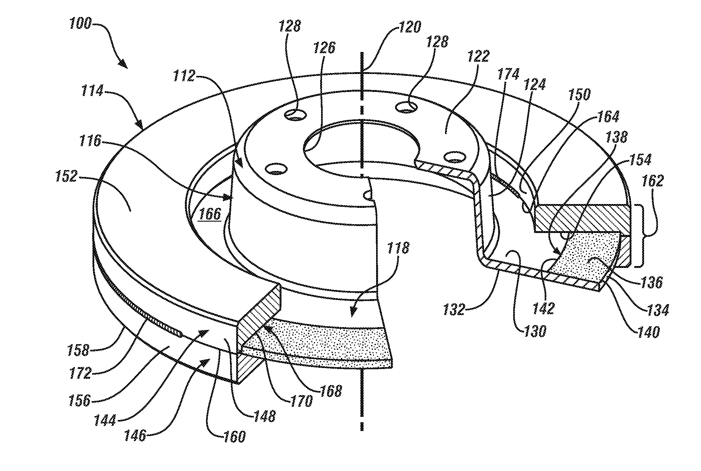
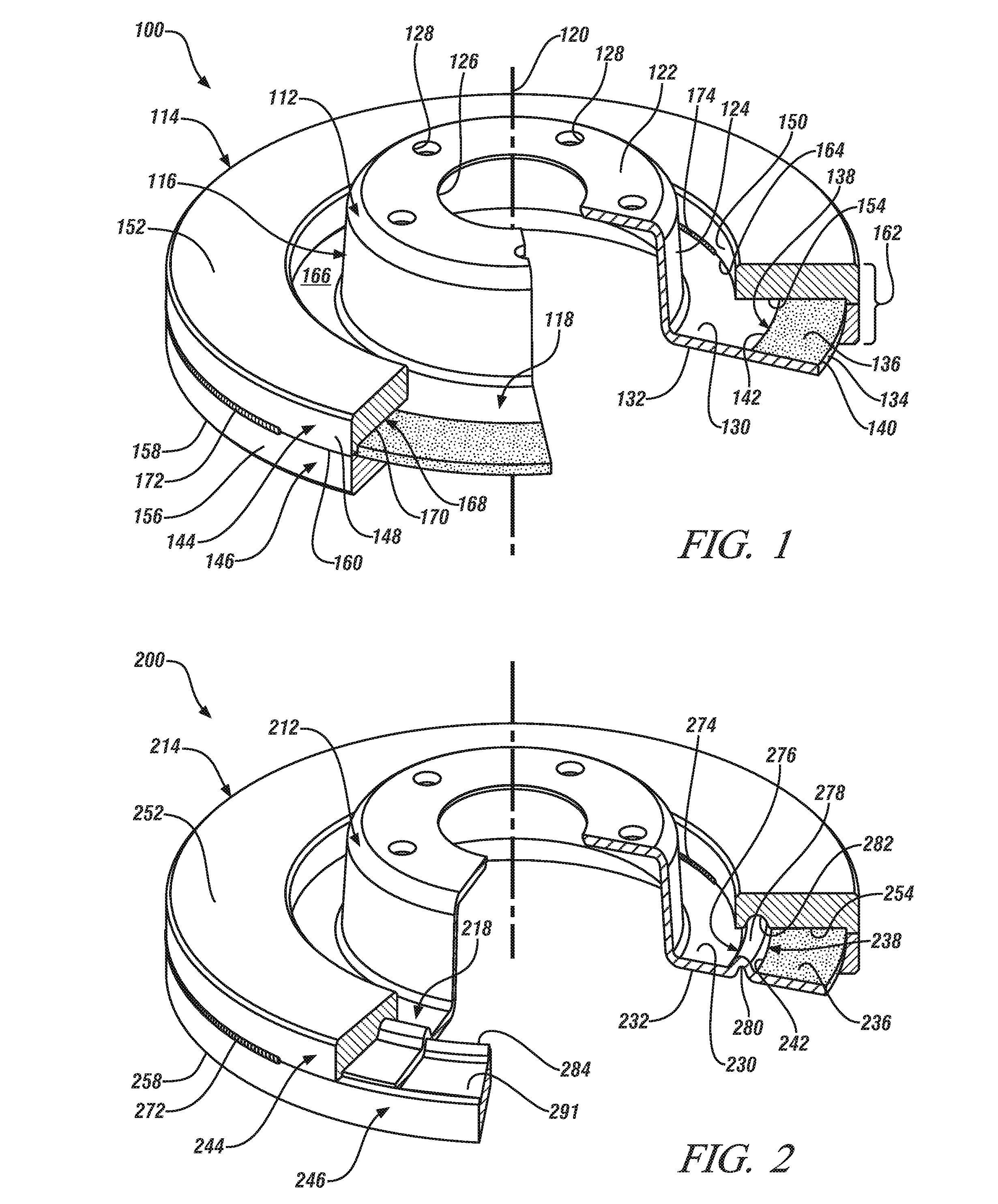
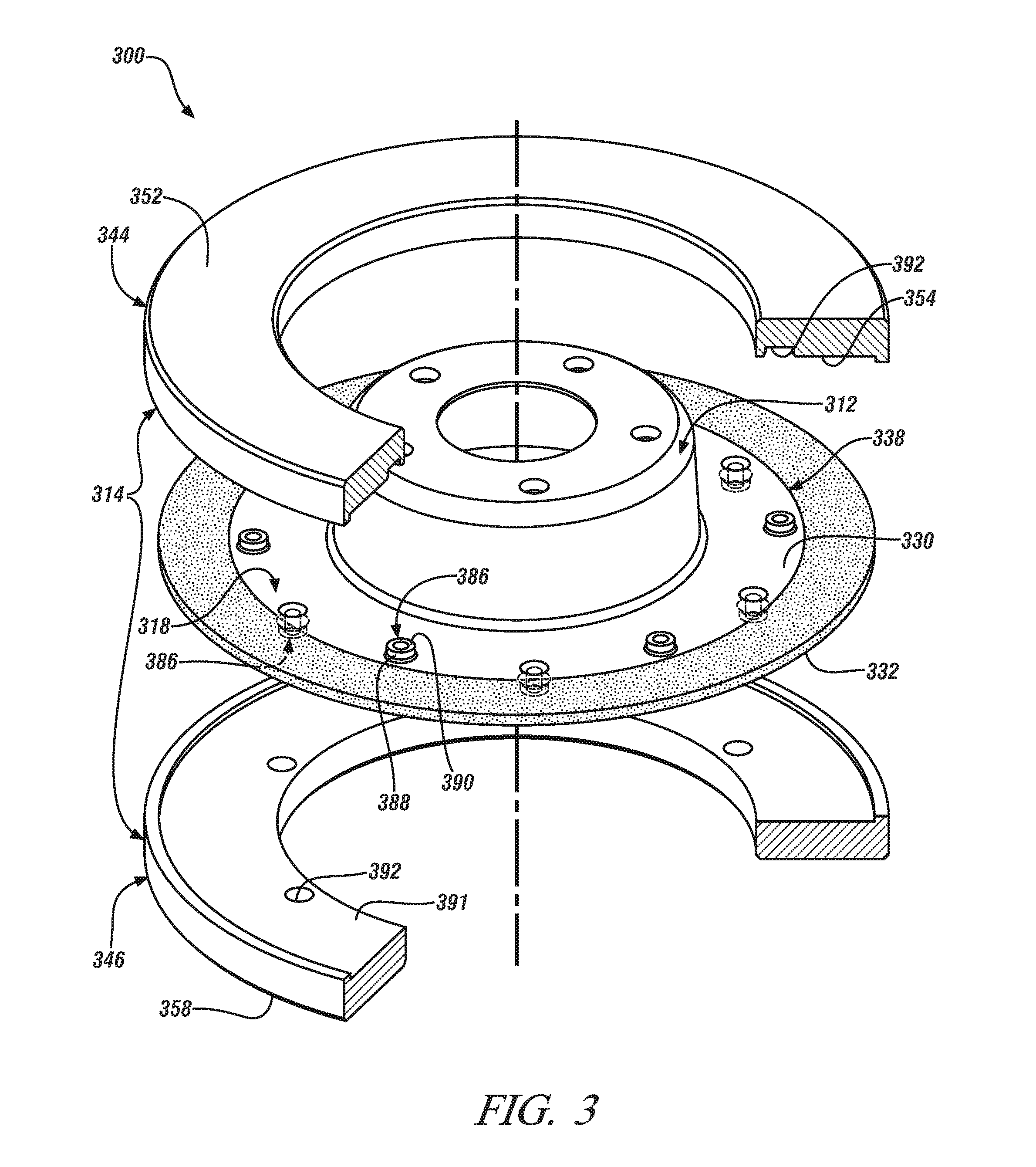
[0025]Several embodiments of a light weight, sound-damped, composite brake rotor for a vehicle braking system are shown in FIGS. 1-13. The brake rotor includes a rotor cheek, which may be solid or vented, supported on a rotor hat. The rotor cheek is formed from two or more separate and distinct cast iron pieces and, when assembled, provides a pair of oppositely-facing annular braking surfaces against which selectively applied brake pads can be pressed during braking. Located within the rotor cheek between the two oppositely-facing braking surfaces is a vibration damping element. The vibration damping element facilitates a physically distinct, non-bonded, surface-to-surface interface where relative frictional contacting movement can occur when the brake pads are applied against the braking surfaces. Such frictional interactions convert mechanical vibratory energy into dissipating thermal energy and ultimately weaken the proliferation of vibrations and their ability to sustain a disru...


PUM

PropertyMeasurementUnit
frequencyaaaaaaaaaa
frequencyaaaaaaaaaa
thicknessaaaaaaaaaa

Abstract

A light-weight and sound-damped brake rotor for a vehicle braking system includes a rotor hat and a rotor cheek supported by the rotor hat. The rotor hat includes an axially-protruding central hub and a flange that extends radially from and circumferentially around the central hub. The rotor cheek, which provides at least one braking surface, is formed from two or more separate and distinct pieces which are fixedly secured to the flange of the rotor hat. Located within the rotor cheek underneath the at least one braking surface is a vibration damping element. The brake rotor derives its vibration-deadening and sound-damping effects from the vibration damping element through the occurrence of relative frictional contacting movement.

Description

TECHNICAL FIELD[0001]The technical field of this disclosure relates generally to a light-weight and sound-damped brake rotor for a vehicle braking system. The brake rotor includes a rotor hat and a rotor cheek. The rotor hat includes a flange extending radially from and circumferentially around a central hub. The rotor cheek is supported on the flange of the rotor hat and is formed from two or more distinct pieces which are fixedly secured to the rotor hat by any suitable approach. Located within the rotor cheek is a vibration damping element that damps vibration propagation through the brake rotor during a braking event. A method for making the light-weight and sound-damped brake rotor is also disclosed.BACKGROUND[0002]A motor vehicle braking system typically includes a brake rotor (sometimes called a disc brake rotor) located at one or more wheels of the vehicle. The brake rotor generally includes a rotor hat and a rotor cheek. The rotor hat is coupled to a rotatable axle to permi...

Claims


Application Information

Patent Timeline
Patent Type & Authority Applications(United States)
IPC IPC(8): F16D65/12B23P11/00
CPCF16D65/12F16D65/0006F16D2065/1316Y10T29/49826F16D2065/1392F16D2065/1372F16D2065/1376F16D2065/132
Inventor HANNA, MICHAEL D.RIEFE, MARK T.SUNDAR, MOHANLOWE, BRENT D.BARTOS, ANDREW L.
Owner GM GLOBAL TECH OPERATIONS LLC
Why Eureka
Try Eureka