Supercharge Your Innovation With Domain-Expert AI Agents!

Image projection apparatus

a technology of image projection and projection device, which is applied in the direction of lighting and heating apparatus, instruments, lighting support devices, etc., can solve the problems of user inability to grab or pinch the handle, the temperature of the handle of the light source unit is also high, and the lamp becomes high

Inactive Publication Date: 2013-05-09
RICOH KK
View PDF3 Cites 16 Cited by
  • Summary
  • Abstract
  • Description
  • Claims
  • Application Information

AI Technical Summary

Benefits of technology

The present invention aims to solve issues in conventional technology. An image projection apparatus includes a light source and a holding member that holds the light source. The holding member has a handle portion with a first flow path for flowing air. This invention provides a more efficient way to hold and cool the light source of an image projection apparatus.

Problems solved by technology

These kinds of lamps become high temperature when emitting light.
However, the handle of the light source unit becomes also high temperature due to heat conductance or heat radiation from the light source.
As a result, when the light unit is to be replaced due to the end of lifetime of the light source during operation of the image projection apparatus, the user cannot grab or pinch the handle.
Therefore, the downtime of the apparatus is disadvantageously long.

Method used


Image

  • Image projection apparatus
  • Image projection apparatus
  • Image projection apparatus

Examples


Embodiment Construction

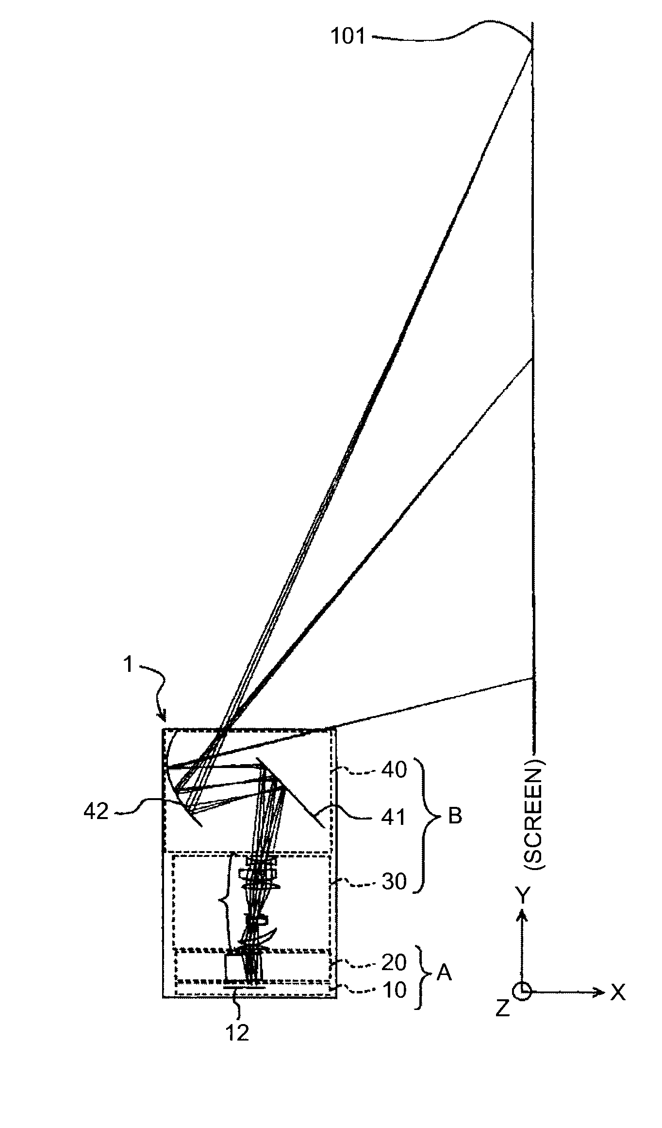
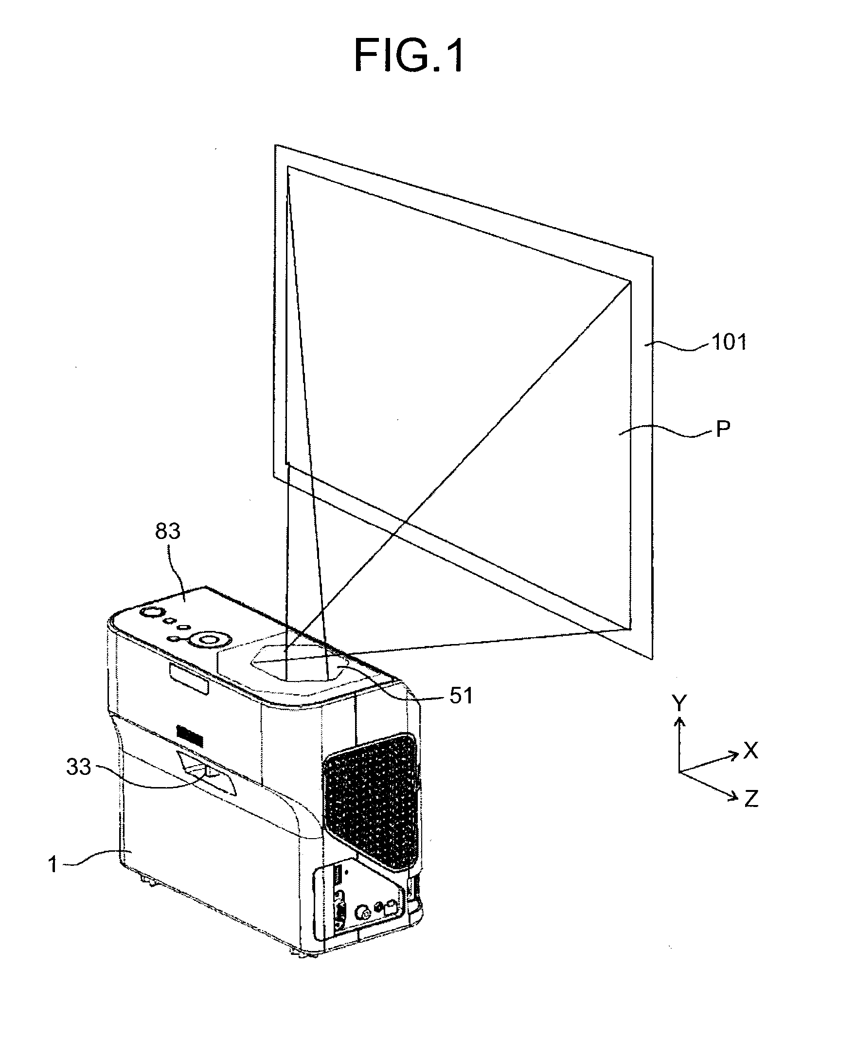
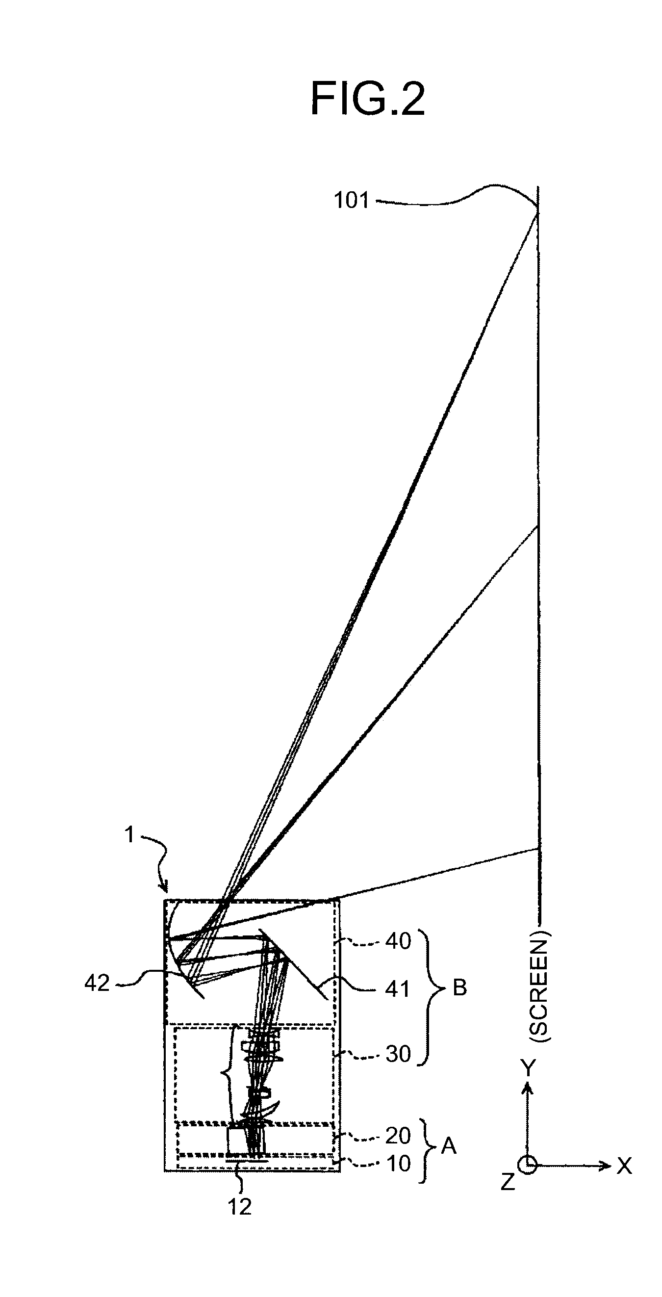
[0043]Hereinafter, embodiments of a projector as an image projection apparatus according to the present invention will be described with reference to the accompanying drawings. FIG. 1 perspectively illustrates a projector 1 and a projection plane 101 such as a screen according to an embodiment. Incidentally, in the following explanation, a normal line direction of the projection plane 101 is referred to as X direction, a short axis direction (vertical direction) of the projection plane 101 is referred to as Y direction, and a long axis direction (horizontal direction) of the projection plane 101 is referred to as Z direction.

[0044]As illustrated in FIG. 1, a transmissive glass 51 from which a projection image P is emitted is disposed at a top surface of the projector 1. The projection image P emitted from the transmissive glass 51 is projected on the projection plane 101 such as a screen.

[0045]Furthermore, at the top surface of the projector 1, an operating part 83 by which a user o...


PUM


Abstract

An image projection apparatus includes a light source, light from which is used to project an image, and a holding member configured to hold the light source. The holding member includes a handle portion, and the handle portion includes a first flow path for flowing air.

Description

CROSS-REFERENCE TO RELATED APPLICATIONS[0001]The present application claims priority to and incorporates by reference the entire contents of Japanese Patent Application No. 2011-242927 filed in Japan on Nov. 4, 2011.BACKGROUND OF THE INVENTION[0002]1. Field of the Invention[0003]The present invention relates to an image projection apparatus.[0004]2. Description of the Related Art[0005]Conventionally, there is known an image projection apparatus provided with an image forming unit to form an image with light emitted from a light source on the basis of image data from a personal computer (PC), video camera or the like, so that the image is projected and displayed on a screen or the like.[0006]As the light source of the image projection apparatus, a halogen lamp, a metal halide lamp, a high pressure mercury lamp and the like may be used. These kinds of lamps become high temperature when emitting light. Therefore, the image projection apparatus is provided with a light source cooling un...

Claims


Application Information

Patent Timeline
Patent Type & Authority Applications(United States)
IPC IPC(8): F21V21/00
CPCG03B21/2093G03B21/16G03B21/20
Inventor FUJIOKA, TETSUYAYAMADA, MASAMICHITSUKIOKA, YASUTADAISHIKAWA, NAOYUKIKANAI, HIDEO
Owner RICOH KK
Features
  • R&D
  • Intellectual Property
  • Life Sciences
  • Materials
  • Tech Scout
  • Unparalleled Data Quality
  • Higher Quality Content
  • 60% Fewer Hallucinations
Learn More