
Random gap insertion in an optical ring network

a random gap and optical ring technology, applied in the field of telecommunications networks, can solve the problems of inability to detect the gap, the gap is not fixed, etc., and achieves the effect of avoiding the gap from being damaged

Inactive Publication Date: 2013-05-09
INTUNE TECH
View PDF0 Cites 5 Cited by
  • Summary
  • Abstract
  • Description
  • Claims
  • Application Information

AI Technical Summary

Benefits of technology

This invention relates to a way to ensure fairness in latency and fair throughput in a network by using random gaps to allocate bandwidth to different sources. The invention controls the random generator to control the size and timing of the gaps, and ensures that different nodes in the network will never have the same gap pattern for the same wavelength. The invention allows for dynamic adjustments based on data activity and improves overall latency by reducing delay variation. The technical effects are improved fairness and reduced delay in data transmission.

Problems solved by technology

In such networks there is an inherent unfairness as the location which is furthest upstream from the destination has un-contended access to that destination and can block closer sources.
The unfairness arises because no two sources can add a burst at the same wavelength such that the bursts appear at the same position in the optic fibre ring.
If this was to occur, both bursts would be corrupted and the information contained within lost.
In the fibre optic spans between nodes in the ring, each wavelength cannot interfere with other wavelengths but if two transmitters put optical bursts onto a fibre optic span at the same wavelength at the same time they will interfere and be corrupted such that they cannot be received at the receiver.
To avoid collisions each node must only add bursts onto wavelengths which are not occupied by bursts from other nodes and this leads to contention such that if two nodes wish to send bursts to one destination then they cannot transmit at the same time.
A problem with this fairness approach is that it is not an efficient way to use the bandwidth or wavelengths in the ring network.
This mechanism is also more complex in that it relies on coordinated control, that is, the sources must receive push back messages from the receivers in order to achieve fairness.
This method of wavelength access control is very complicated both in maintaining synchronisation across the ring and in scheduling access.

Method used


Image

  • Random gap insertion in an optical ring network
  • Random gap insertion in an optical ring network
  • Random gap insertion in an optical ring network

Examples


Embodiment Construction

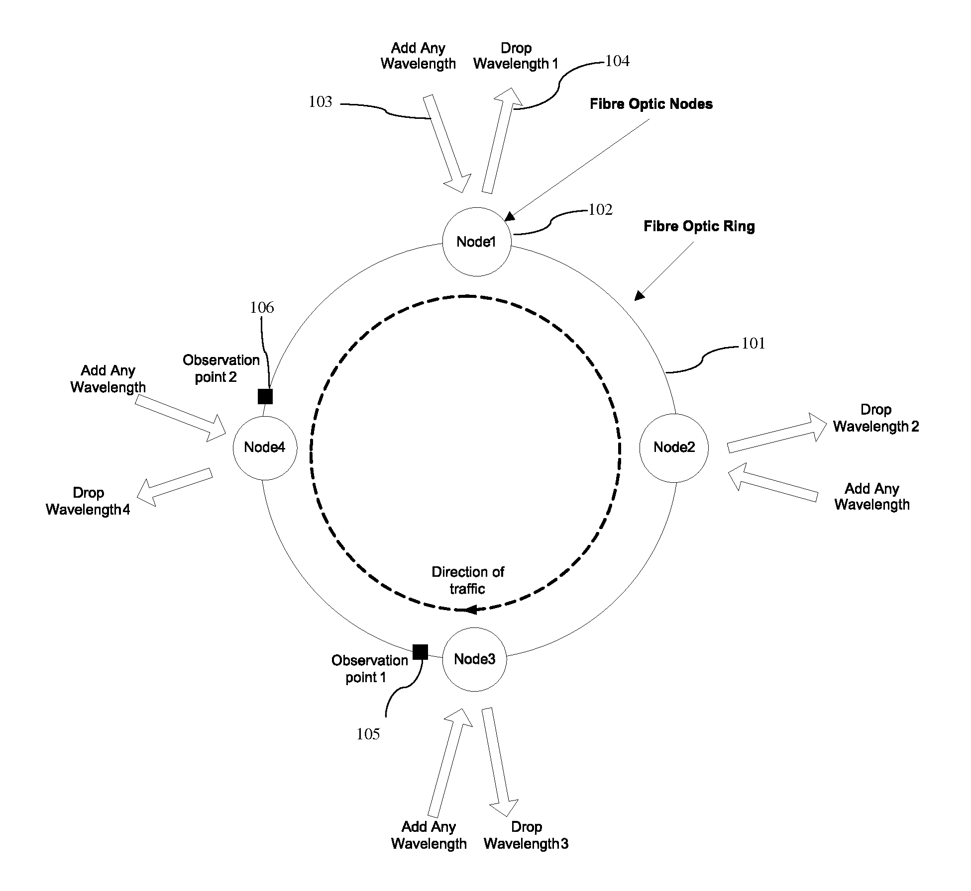
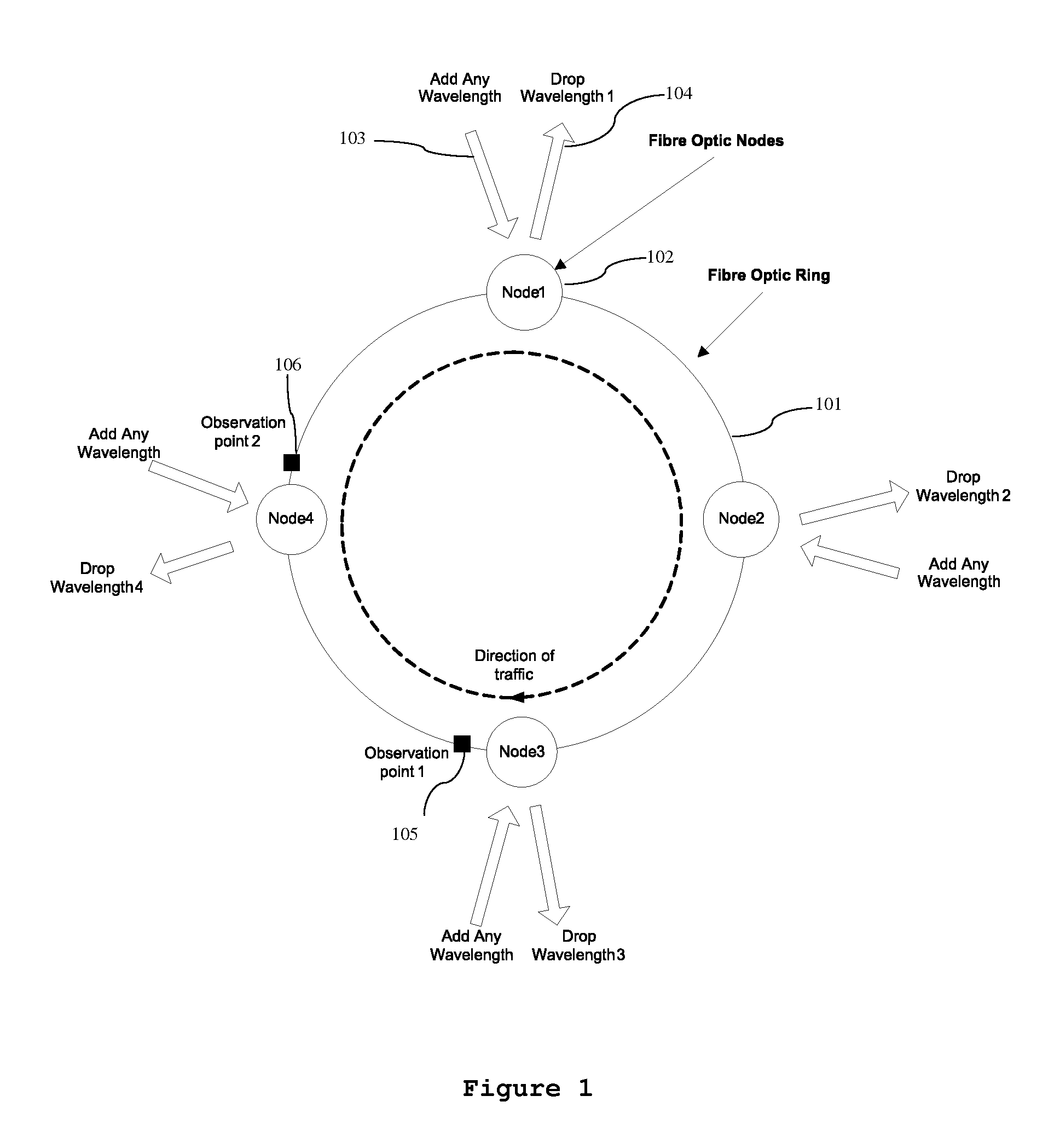
[0059]FIG. 6 shows the primary aspect of the invention for the same scenario as the previous example. In this case the decision to transmit at all nodes is randomised, so that for periods an upstream node is not allowed to transmit even if it has traffic to send, it has an allocation and the wavelength is free. This has the effect of splitting out the large bursts shown in FIG. 5 into multiple smaller bursts and similarly for node 3. The probability that bursts align is smaller and Node 4 can now fill in the gaps and can achieve more than 50% throughput.

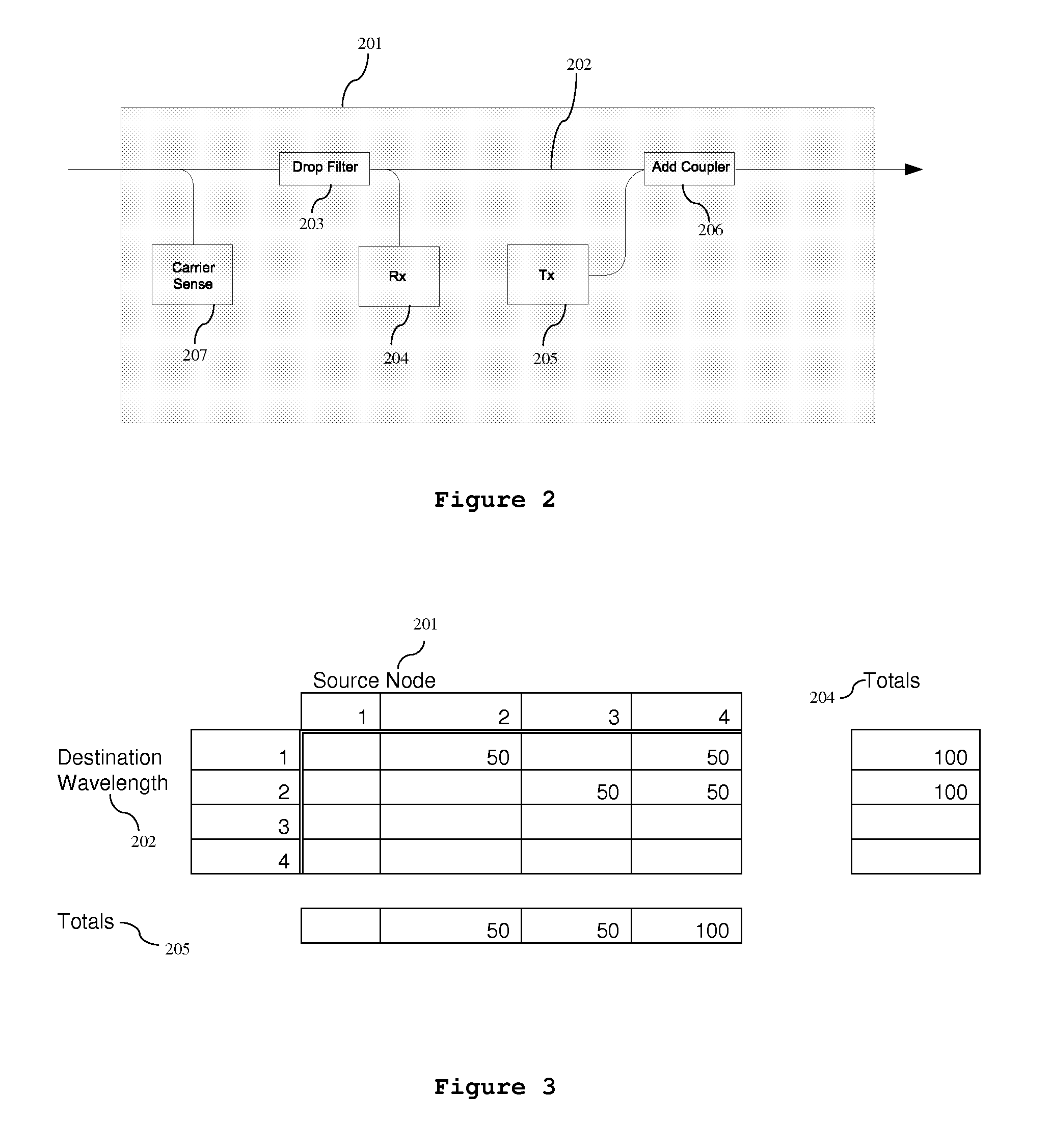
[0060]The invention is used at each source to control the insertion and size of gaps for a wavelength by terminating bursts and preventing further transmission at the same wavelength for a determined time. The invention, therefore, controls the size of all bursts and the size of all gaps for all wavelengths at each source node. For the example allocations shown in FIG. 3, the worst case access received by Node 4 is 50%, as shown in F...


PUM


Abstract

The invention provides a burst transmission optical fibre wavelength routed ring network and method comprising a plurality of nodes on a network ring where each node can drop and add a wavelength. The network has a control means to control the wavelength to be transmitted on the network ring in a burst transmit mode from each node over a scheduling interval. The invention provides a random generator for generating a plurality of gap intervals over the scheduling interval, such that the gap intervals allow for wavelengths from different nodes to transmit wavelengths in said gaps to achieve a fair access to bandwidth and fair latency in the ring network.

Description

FIELD OF THE INVENTION[0001]The invention relates to a telecommunications network. In general the invention relates to a control system and method to achieve fair access to bandwidth and fair latency between nodes that asynchronously share a transmission medium. In particular it relates to a control system and method to achieve fair access to bandwidth and fair latency between nodes through a fibre optic burst mode ring network.BACKGROUND TO THE INVENTION[0002]A typical instantiation of a fibre optic burst mode ring network uses tunable lasers at the ingress transmit side, where the laser is tuned to a specific wavelength that is received by a specific location on the ring. Optical filters are used to drop different wavelengths at different locations on the ring. In this type of network ingress network traffic with a common destination is formed into bursts which are transmitted at the correct wavelength to get the bursts and traffic contained within to their destination.[0003]In su...

Claims


Application Information

Patent Timeline
IPC IPC(8): H04B10/275
CPCH04B10/275H04J14/0283
Inventor FARELL, TOMO'NEILL, SHANE
Owner INTUNE TECH
Learn More