Fuel cell

a fuel cell and cell technology, applied in the field of fuel cells, can solve the problems of reducing the size or miniaturization of the fuel cell, and achieve the effect of convenient and reliable relative positioning

Active Publication Date: 2013-05-09
NISSAN MOTOR CO LTD
View PDF3 Cites 8 Cited by
  • Summary
  • Abstract
  • Description
  • Claims
  • Application Information

AI Technical Summary

Benefits of technology

[0006]According to the fuel cell of the present invention, a pair of separators may be easily and reliably positioned relative to the frame and MEA by a periphery portion of manifold hole associated with frame body and these may be integrated eventually. Moreover, according to the described fuel cell, the space for the space for placing a protrusion for positioning is not required, it is possible to realize the miniaturization of the fuel cell.

Problems solved by technology

However, in the fuel cell of such prior art described above, since as a configuration in which the frame-integrated MEA and a pair of separators are united, a plurality of projections along with step portions are provided, a space for these placements are required, which would be a disadvantage for the miniaturization or reduction in size of the fuel cell.

Method used


Image

  • Fuel cell
  • Fuel cell
  • Fuel cell

Examples


Embodiment Construction

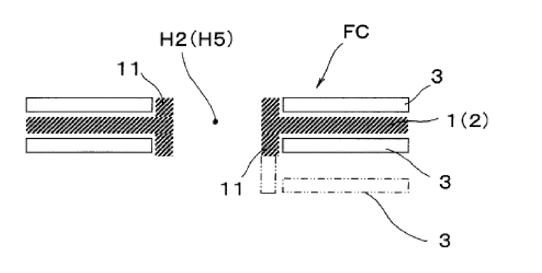
[0023]Now, with reference to the drawings, a description of an embodiment of the fuel cell according to the present invention will be made. It should be noted that, for the convenience of explanation, the up and down direction of the drawing corresponds to a stacking direction of the fuel cell, and the anode side of the MEA is defined as an upper side while the cathode side is defined as a lower side. In practice, however, the anode side and the cathode side may be reversed, and the stacking direction is also not limited to the up and down direction.

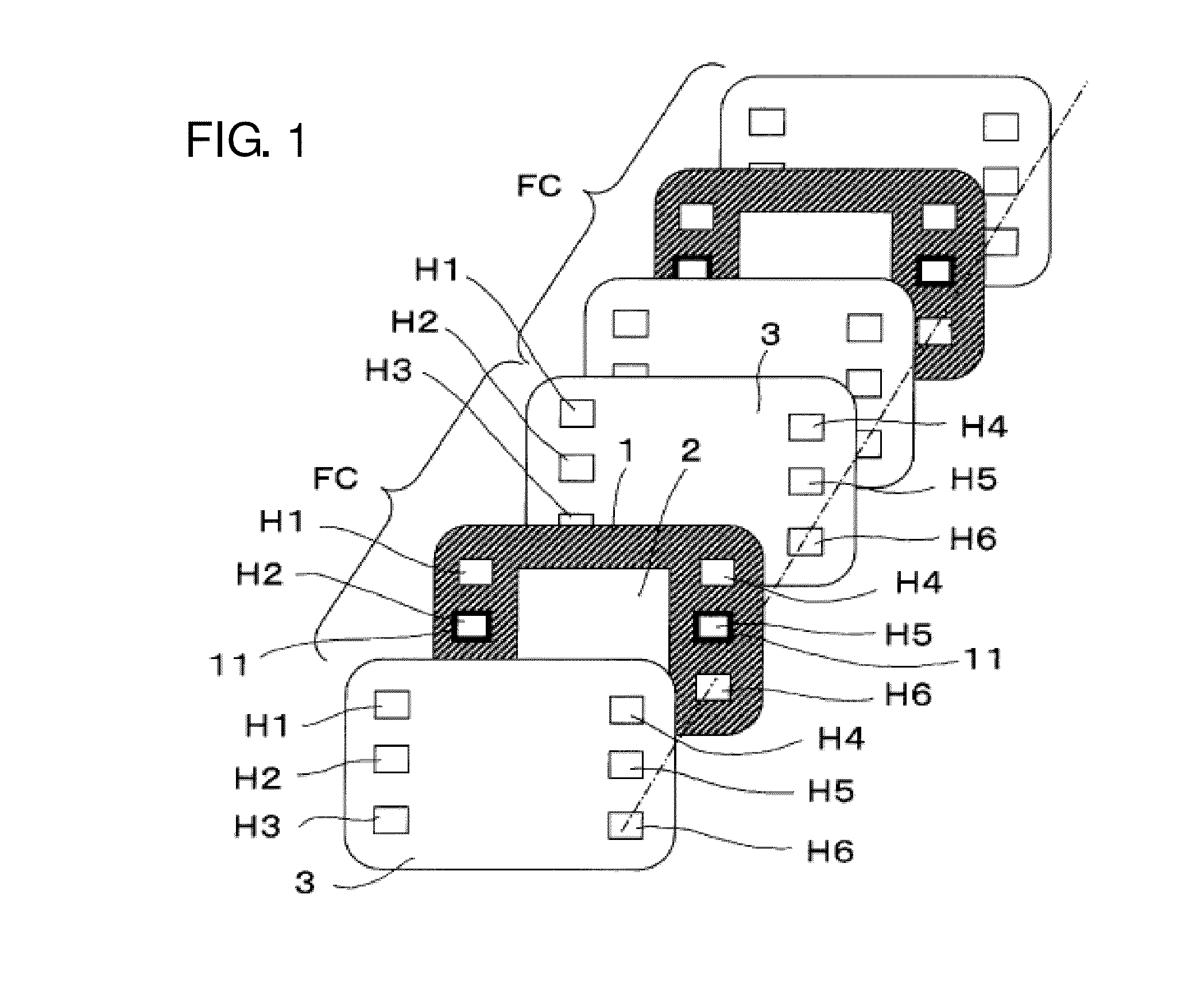
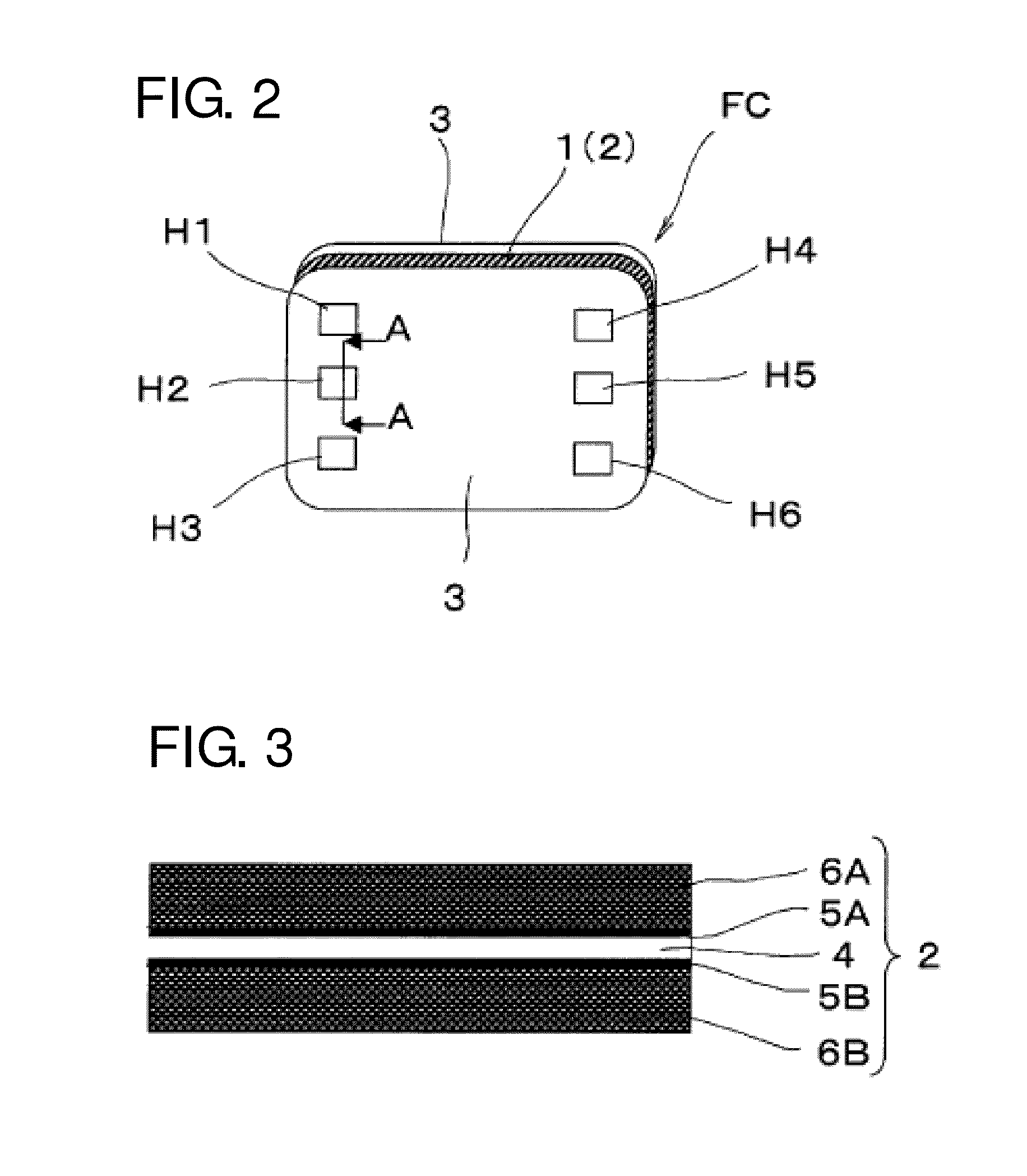
[0024]The fuel cell shown in FIGS. 1 to 3 has a membrane-electrode-assembly (NEA) structure 2 having a frame 1 around its periphery and a pair of sheets of separators 3, 3. In addition, a structure is provided to distribute or circulate reactant gas between frame 1 and separator 3, 3.

[0025]The film or membrane structure 2 is generally called MEA (Membrane Electrode Assembly) and is configured as shown in particular in FIG. 3 to have an e...


PUM

PropertyMeasurementUnit
flexibilityaaaaaaaaaa
areaaaaaaaaaaa
angleaaaaaaaaaa

Abstract

A fuel cell is provided with a membrane electrode assembly provided with a frame, both of which are sandwiched between two separators. The fuel cell is configured such that reactive gas is circulated between the frame and the separators. The frame and both separators each have manifold holes, the rims of the manifold holes of frame extend into the manifold holes in the separators, and protrusions cover the inner peripheral surfaces of the manifold holes in at least one of the separators. This structure makes possible the easy and accurate position and integration of the separators and the frame, and fuel cell miniaturization can be achieved because space to position the protrusions is not needed.

Description

TECHNICAL FIELD[0001]The present invention relates to a fuel cell used as a fuel cell power generating element, in particular, the present invention relates to a fuel cell that makes up a fuel cell stack by stacking a plurality of such cells.BACKGROUND[0002]The fuel cell described in WO2007-123191 is provided with a membrane-electrode-assembly (MEA) integrating a frame body and a pair of separators sandwiching the MEA. In addition, at several locations on the frame body, projections with a hook-shaped tip are provided while at several locations on the separators, step portions are provided. By engaging respective projections with associated step portions, the frame-integrated type MEA and the pair of separators are united or integrated.[0003]However, in the fuel cell of such prior art described above, since as a configuration in which the frame-integrated MEA and a pair of separators are united, a plurality of projections along with step portions are provided, a space for these plac...

Claims


Application Information

Patent Timeline
Patent Type & Authority Applications(United States)
IPC IPC(8): H01M8/10
CPCY02E60/521H01M8/10H01M8/1004H01M8/02H01M8/24H01M8/242H01M8/0206H01M8/0254H01M8/0273H01M8/0276H01M8/0284H01M2008/1095Y02E60/50H01M8/2483
Inventor OKU, TAKANORIABE, MITSUTAKAUEHARA, SHIGETAKANUMAO, YASUHIRO
Owner NISSAN MOTOR CO LTD
Why Eureka
Try Eureka