
System and Method for the Analysis of Electrocardiogram Signals

a technology of electrocardiogram and system, applied in the field of system and method for the analysis of electrocardiogram (ecg) signals, can solve the problems of requiring at least high computational complexity, compromising the life of patients, and requiring algorithms in portable systems to extract information from noisy signals. , to achieve the effect of less computational complexity

Inactive Publication Date: 2013-05-09
INTERUNIVERSITAIR MICRO ELECTRONICS CENT (IMEC VZW)
View PDF2 Cites 9 Cited by
  • Summary
  • Abstract
  • Description
  • Claims
  • Application Information

AI Technical Summary

Benefits of technology

This patent is about a way to calculate a continuous wavelet transform. One way to do this is by using a unit scale continuous wavelet transform, which requires less computational complexity. The technical effect of this innovation is more efficient and accurate data analysis.

Problems solved by technology

Any abnormalities detected at this stage may indicate the existence of a heart condition, such as arrhythmia, which can be fatal and requires continuous monitoring to ensure the occurrence of the faster, slower or irregular heart rhythms.
In this case, accuracy in detecting such abnormalities is of paramount importance since a wrong reading of the data received can compromise the life of the patient.
Besides these constraints, an additional challenge for the embedded algorithms in portable systems is the extraction of information from noisy signals.
Known techniques presented in the state-of-the-art require at least high computational complexity and as a result most of them are not applicable in a low power embedded application.
A problem with this solution though is that it is not accurate and reliable enough to be applied for the calculation of the heart bit rate variability (HBRV).

Method used


Image

  • System and Method for the Analysis of Electrocardiogram Signals
  • System and Method for the Analysis of Electrocardiogram Signals
  • System and Method for the Analysis of Electrocardiogram Signals

Examples


Embodiment Construction

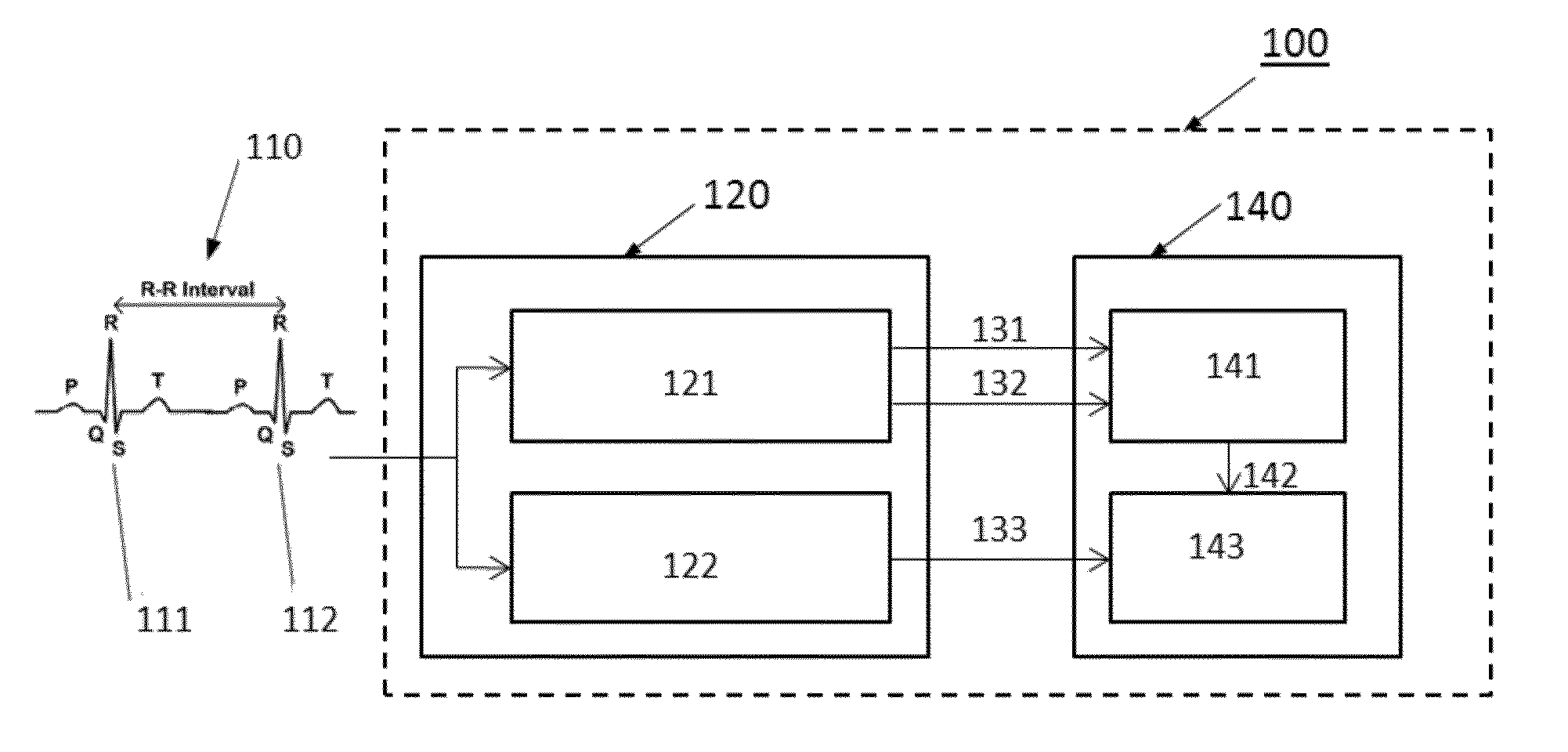
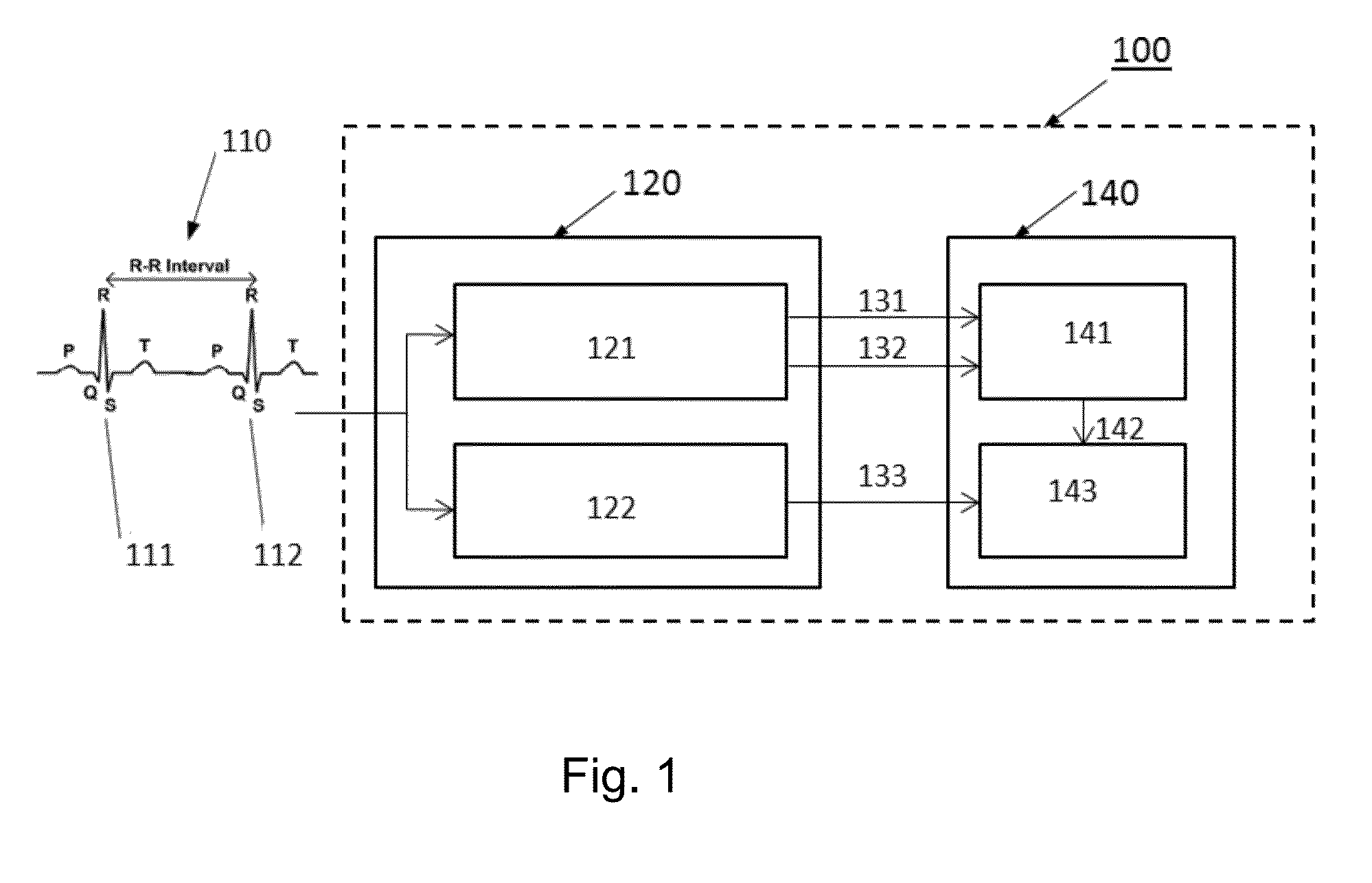
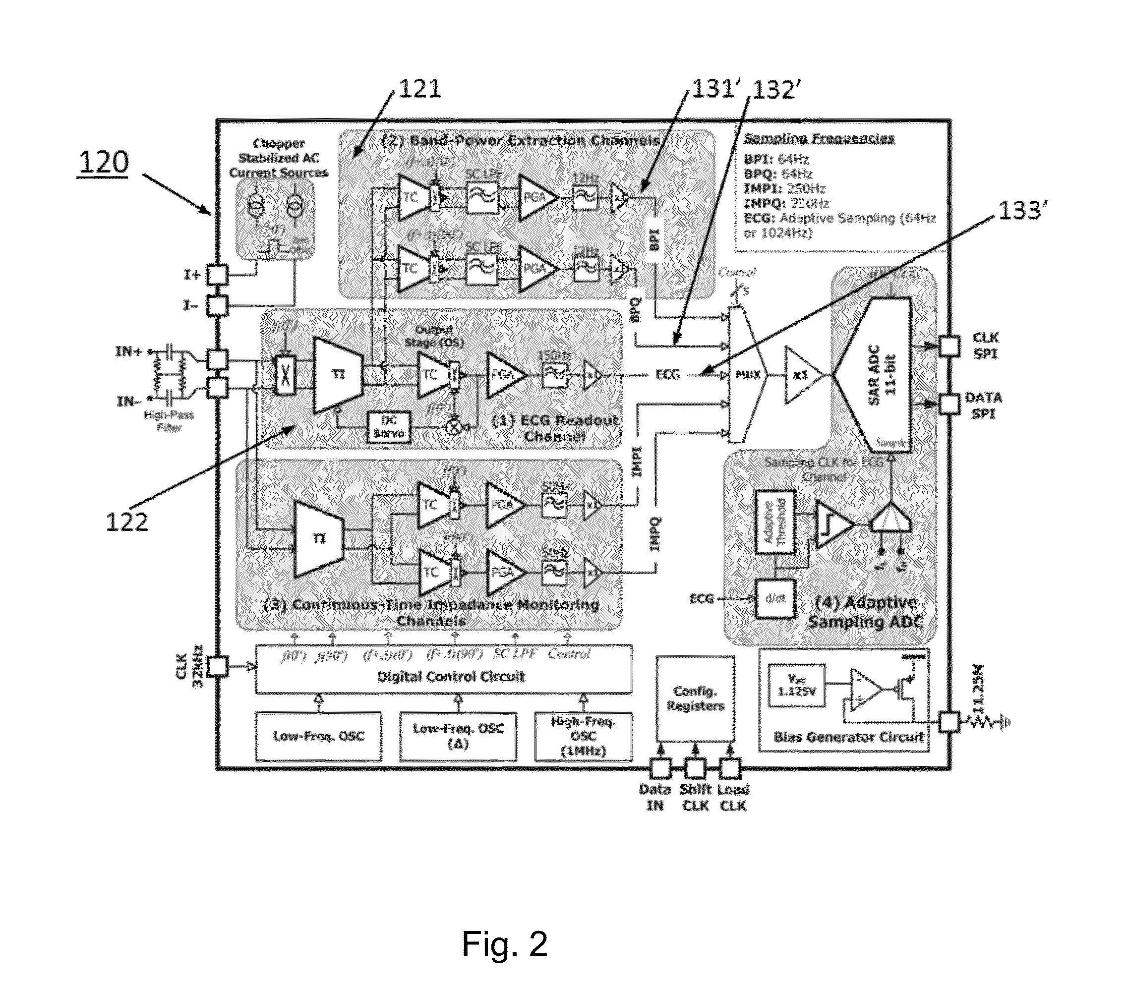
[0023]FIG. 1 shows a simplified block diagram of an exemplary embodiment of a system 100 for the analysis of an input analogue ECG signal 110, with the presence of a successive QRS complex 111 and 112. The system 100 comprises an analogue signal processing circuit 120 or front end and a microprocessor 140 adapted to receive and process signals provided by the analog signal processing circuit 120. The analogue signal processing circuit 120 comprises an electrocardiogram readout channel unit 122 adapted to generate a digital ECG signal version 133 derived from the received analogue ECG signal 110; and a band power extraction channel unit 121 adapted to generate digital in-phase 131 and quadrature phase 132 band power signal components derived from the received analogue ECG signal 110. The microprocessor 140 comprises a beat detection unit 141, providing a valid beat detection signal 142, and an R peak detection unit 143. It is understood that the functions of the microprocessor 140 he...


PUM


Abstract

A microprocessor configured to receive and process digitized signals derived from an analogue ECG signal is provided. An example microprocessor comprises a beat detection unit configured to receive the in-phase and quadrature phase band power signals, calculate a band power value and an adaptive threshold value, and compare said band power value with said adaptive threshold value to detect a QRS complex of the ECG signal indicative of a detected valid beat; and an R peak detection unit configured to receive the digital ECG signal and information about the detected valid beat, select a portion of the received ECG signal as a first time window around the detected valid beat; determine the location of a first R peak position; and perform a time domain search in a second time window around said first R peak position in order to refine the location of an R peak position.

Description

CROSS-REFERENCE TO RELATED APPLICATIONS[0001]This application claims priority under 35 U.S.C. §119(e) to U.S. Provisional Patent Application Ser. No. 61 / 555,321, filed on Nov. 3, 2011, and entitled “Method and System for Evaluating and Detecting Dynamically Changing Biopotential Electrical Signals”, the full disclosure of which is incorporated herein by reference.BACKGROUND[0002]1. Technical Field[0003]The present disclosure is related to a system and method for the analysis of electrocardiogram (ECG) signals and more particularly to the detection and location of the R peaks of an input ECG signal.[0004]2. Technical Background[0005]Monitoring of biopotential electrical signals is currently used in many applications. For example, ambulatory monitoring of an electrocardiogram (ECG) taken from a biological subject (patient) can be used to evaluate the heart condition of a patient, like ischemia, late potentials, heart rate variability etc. This is normally performed by measuring the pa...

Claims


Application Information

Patent Timeline
IPC IPC(8): A61B5/0456A61B5/352
CPCA61B5/726A61B5/0456A61B5/04017A61B5/316A61B5/352A61B5/346
Inventor YAZICIOGLU, REFET FIRATTORFS, TOMSHRESTHA, SACHIN
Owner INTERUNIVERSITAIR MICRO ELECTRONICS CENT (IMEC VZW)
Learn More