
Breast Implant with Low Coefficient of Friction Between Internal Shells in an Aqueous Fluid Environment

a technology of internal shells and friction coefficients, applied in the field of surgically implantable prosthetic devices, can solve the problems of inability to detect lack of proper appearance and tactile properties of prior art saline solution filled prosthetic devices, and difficulty in detecting the rupture of the envelope of a silicone gel implant, etc., to achieve low friction coefficient, prevent intermittent sticking and friction between the interacting shells, and high sliding ability

Active Publication Date: 2013-05-09
PARADIGM MEDICAL
View PDF18 Cites 11 Cited by
  • Summary
  • Abstract
  • Description
  • Claims
  • Application Information

AI Technical Summary

Benefits of technology

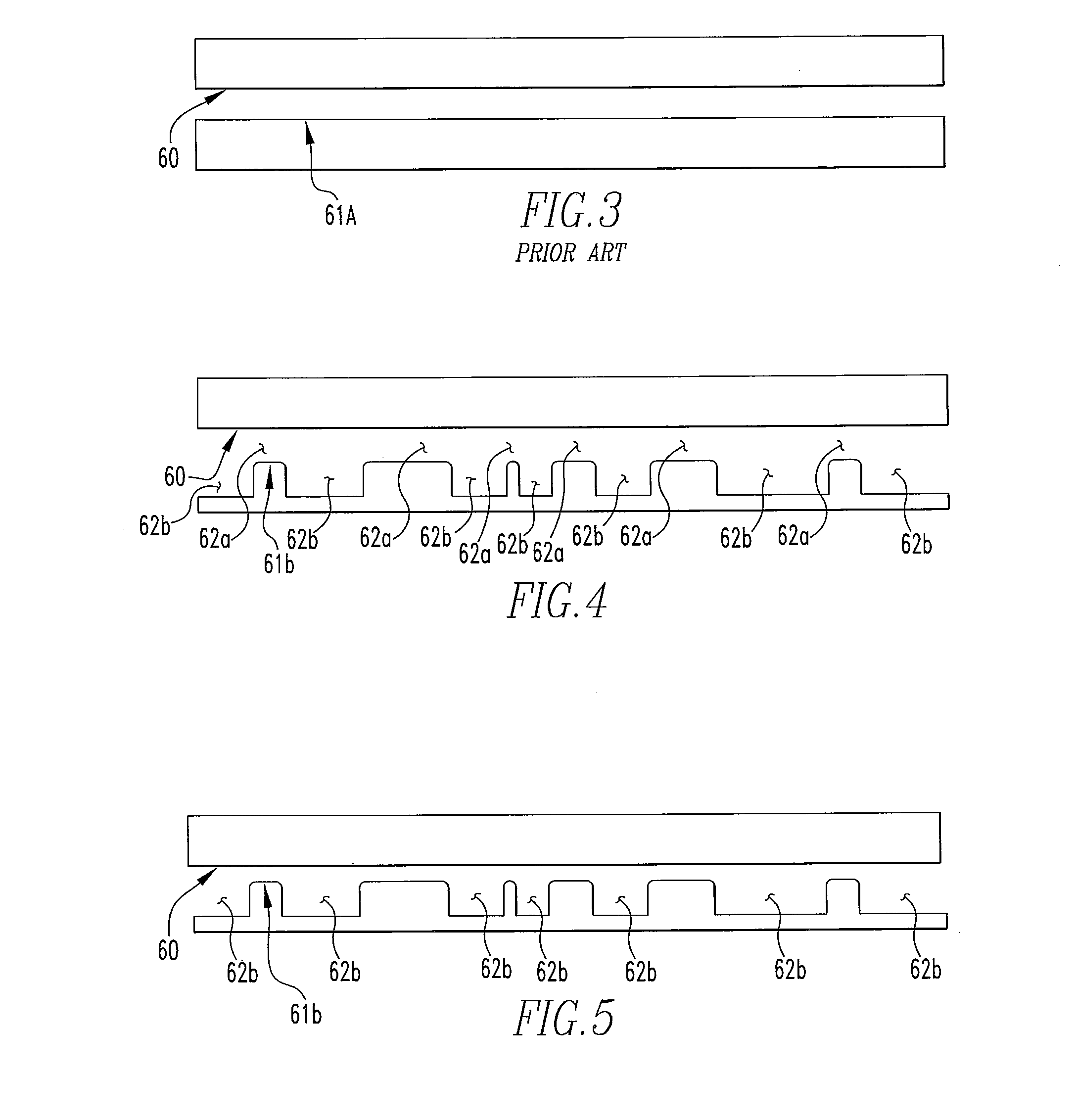
The invention is a prosthetic device that uses saline or similar substances to provide a safe and harmless implant. The design of the device prevents the outer shell from rupturing and allows the saline to be absorbed into the body tissue safely, without the need for additional diagnostic tests like an MRI scan. The arrangement of the lumens and non-enclosing fitted shells reduces the displacement rate of the fluid, improving the feel of the implant compared to previous designs. The surface of the interacting shells is textured to provide a low coefficient of friction and high slidability over an adjacent shell, without the need for additional lubricant. This improves the tactility and feel of the implant. Only one surface of each interacting surface pair needs to be textured for this invention, but both surfaces could be textured for improved effect.

Problems solved by technology

Prior art silicone gel devices have tactile properties similar to normal tissue, but suffer from certain disadvantages.
First, some silicone may bleed through the envelope and migrate out of the implant into the tissue, or into an adjacent saline filled compartment of the implant.
Second, rupture of the envelope of a silicone gel implant is difficult for a patient to detect, and may require a Magnetic Resonance Imaging (MRI) scan for diagnosis.
The prior art saline solution filled prosthetic devices suffer from certain disadvantages and lack the proper appearance and tactile properties due to several factors.
First, the saline solution displaces too quickly to give the proper tactile properties.
Second, the ease of displacement of the saline solution can create a “fluid wave” in the implant presenting an unnatural look of the prosthetic device.
Third, when the saline solution displaces from one area of the implant, the lack of volume in that area may result in visible wrinkling of the shell.
Fourth, the outer shell can fold upon itself, causing an area of wear (e.g., fold-flaw), leading to failure and deflation.
The drawback to such prior art baffle-forming material is that such material may not match the single layer structure, geometry, proportions, etc., of the envelope, thereby resulting in wrinkling and folding of the implant due to the uncontrolled position of the baffle-forming material.
Additionally, some of the prior art baffle material can bunch up in a portion of the implant and be felt through the shell, resulting in an unnatural feel to the implant.
While organic polymers, protein fluids and added lubricating agents may provide a consistent lubricating layer between the various interacting shells within the implant, in the event of rupture, they may cause an undesirable tissue response.
However, saline may not provide a consistent lubricating layer between the various interacting shells within the implant, which may allow the shells in some areas of the implant to intermittently stick together and give the implant an undesirable tactile feel.

Method used


Image

  • Breast Implant with Low Coefficient of Friction Between Internal Shells in an Aqueous Fluid Environment
  • Breast Implant with Low Coefficient of Friction Between Internal Shells in an Aqueous Fluid Environment
  • Breast Implant with Low Coefficient of Friction Between Internal Shells in an Aqueous Fluid Environment

Examples


Embodiment Construction

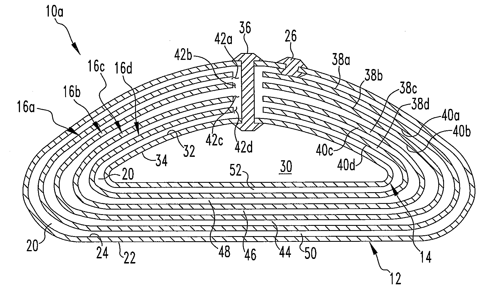
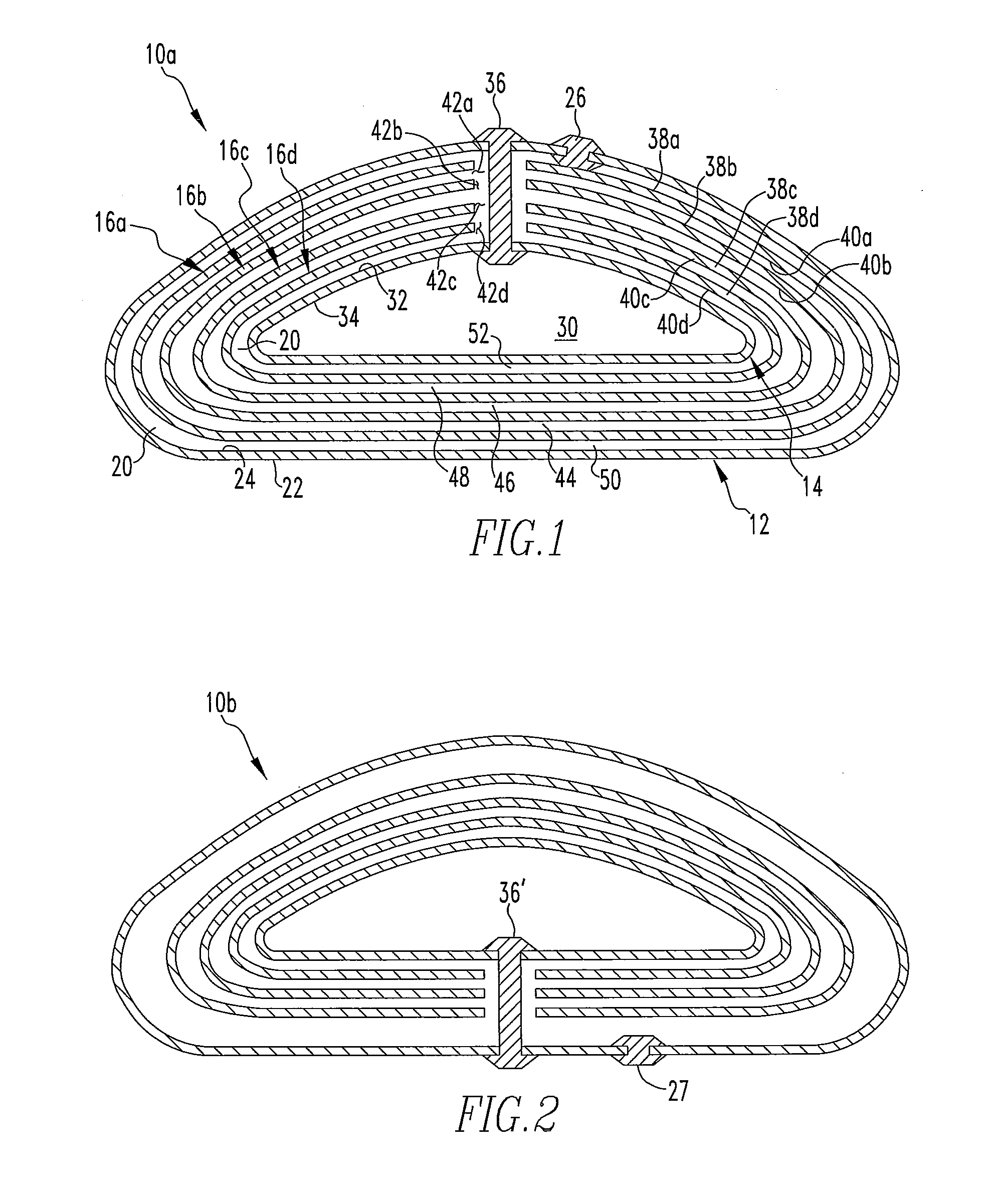
[0028]Referring to FIGS. 1 and 2, implants 10a and 10b are particularly adapted for use as a surgically-implantable mammary prosthesis. The implant 10a of FIG. 1 includes an outer shell 12 enclosing a lumen or a compartment, an inner shell 14 enclosing a lumen or a compartment, and one or more generally dome-shaped non-enclosing fitted shells, e.g., a first non-enclosing fitted shell 16a, a second non-enclosing fitted shell 16b, a third non-enclosing fitted shell 16c and a fourth non-enclosing fitted shell 16d. The inner shell 14 and outer shell 12 are typically sealed with silicone “patches” by means known to those skilled in the art. In a particularly desirable embodiment, with reference to the implant 10a as it is oriented in the drawing, the dimensions of the outer shell 12 and the inner shell 14 are defined by a diameter measurement and a projection measurement. The diameter measurement is representative of the width of the implant 10a at its widest point and the projection mea...


PUM


Abstract

A fluid-filled surgically-implantable prosthetic device encloses one or more non-enclosing fitted shells arranged adjacent to and in a graduated relation to each other. The invention relates specifically to implantable breast prostheses with a low coefficient of friction between two or more interacting elastomeric shells in an aqueous fluid environment, without the addition of a lubricating agent to the fluid.

Description

BACKGROUND OF THE INVENTION[0001]1. Field of the Invention[0002]This invention relates generally to surgically-implantable prosthetic devices and, more specifically, to breast prostheses. The invention relates specifically to implantable breast prostheses with a low coefficient of friction between two or more interacting elastomeric shells in an aqueous fluid environment, without the addition of a lubricating agent to the fluid.[0003]2. Description of Related Art[0004]It has become a practice in the field of surgery to place a prosthetic implant in various areas of the body under any one of various conditions. In cases where cancerous, precancerous, or other abnormal or damaged tissue has been removed, the prosthetic implant is often used as a replacement for the removed tissue. Its purpose is to restore the original body contour. An implant of this character provides physical support for the surrounding body tissue. By filling any voids that are created by the removal of the body t...

Claims


Application Information

Patent Timeline
IPC IPC(8): A61F2/12
CPCA61F2/12
Inventor HAMAS, ROBERT S.BACK, DWIGHT D.
Owner PARADIGM MEDICAL
Learn More