Eureka AIR delivers breakthrough ideas for toughest innovation challenges, trusted by R&D personnel around the world.

Hydraulic system and method for a hybrid vehicle

Active Publication Date: 2013-05-16
ALLISON TRANSMISSION INC
View PDF2 Cites 22 Cited by
  • Summary
  • Abstract
  • Description
  • Claims
  • Application Information

AI Technical Summary

Benefits of technology

This patent describes a compact hydbrid module design for vehicles that reduces the need for modifications to other systems. The hybrid system includes its own lubrication and cooling systems that are able to operate independently of the transmission and engine. The module uses a dual mechanical / electric pump system to reduce the size and weight of the required mechanical pump. The design also addresses issues related to piston pressure control and prevents power loss of the torque converter by keeping the area around it dry. Overall, the invention improves the efficiency and performance of the hydbrid module in vehicles.

Problems solved by technology

While numerous hybrid systems have been proposed, the systems typically require significant modifications to the drive trains of the vehicles.
These modifications make it difficult to retrofit the systems to existing vehicles.
Moreover, some of these systems have a tendency to cause significant power loss, which in turn hurts the fuel economy for the vehicle.
The compact design of the hybrid module has placed demands and constraints on a number of its subcomponents, such as its hydraulics and the clutch.
The recess for the spring in the piston creates an imbalance in the opposing surface areas of the piston.
This imbalance is exacerbated by the high centrifugal forces that cause pooling of the fluid, which acts as the hydraulic fluid for the piston.
As a result, a nonlinear relationship for piston pressure is formed that makes accurate piston control extremely difficult.
The fluid has a tendency to leak from the hybrid module and around the torque converter.

Method used


Image

  • Hydraulic system and method for a hybrid vehicle
  • Hydraulic system and method for a hybrid vehicle
  • Hydraulic system and method for a hybrid vehicle

Examples


Embodiment Construction

[0033]For the purposes of promoting an understanding of the disclosure, reference will now be made to the embodiments illustrated in the drawings and specific language will be used to describe the same. It will nevertheless be understood that no limitation of the scope of the disclosure is thereby intended, such alterations and further modifications in the illustrated device and its use, and such further applications of the principles of the disclosure as illustrated therein being contemplated as would normally occur to one skilled in the art to which the disclosure relates.

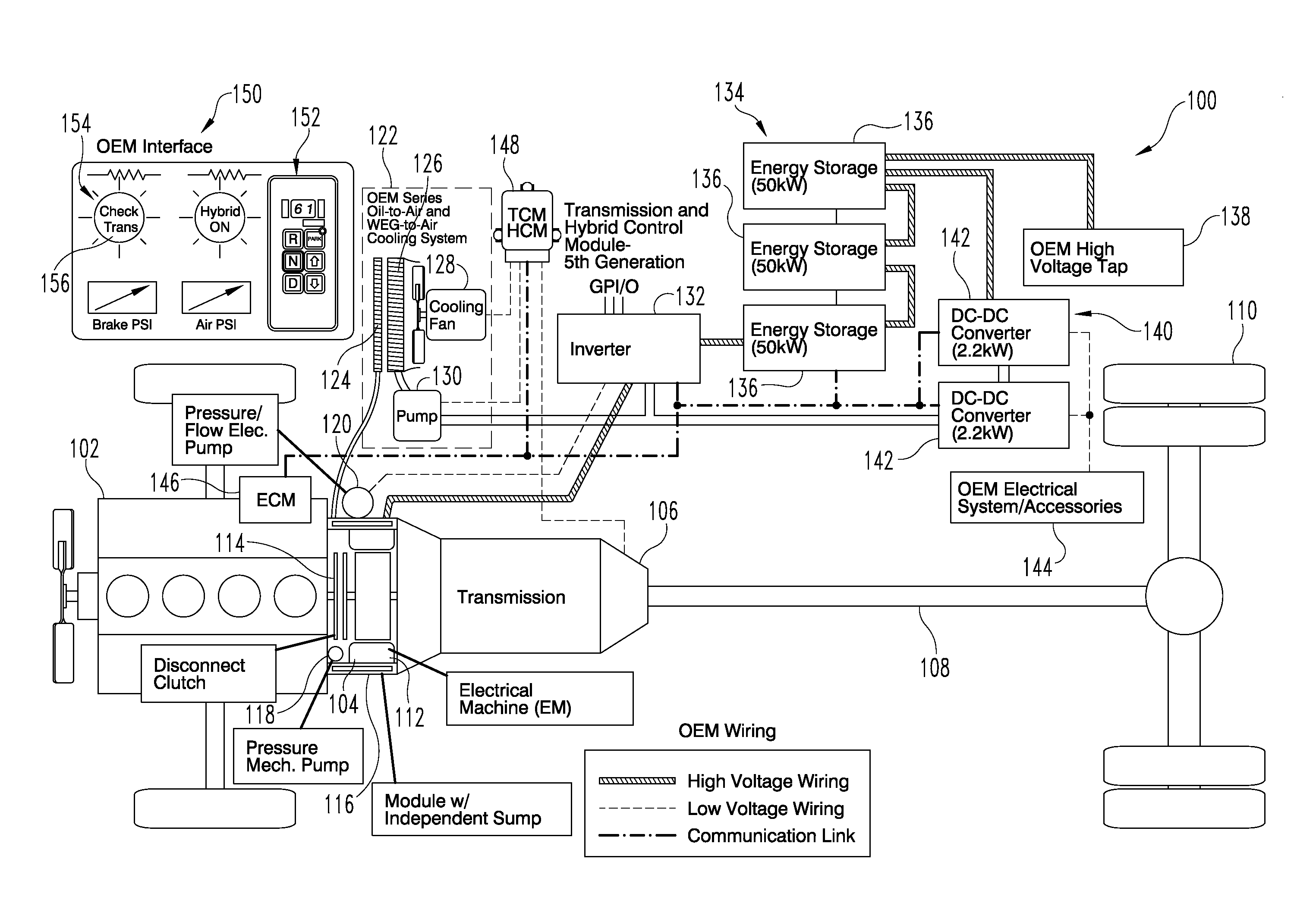
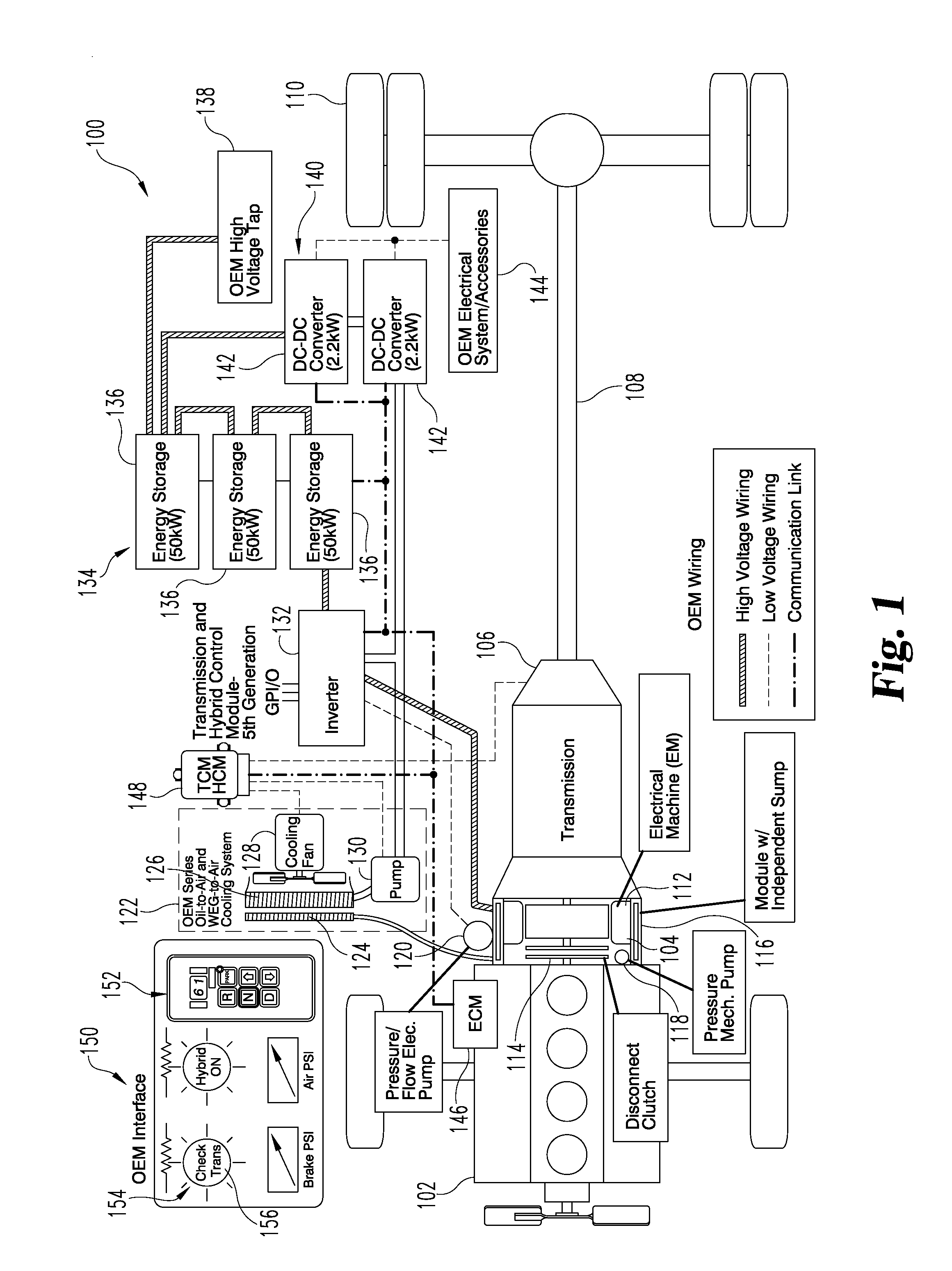
[0034]FIG. 1 shows a diagrammatic view of a hybrid system 100 according to one embodiment. The hybrid system 100 illustrated in FIG. 1 is adapted for use in commercial-grade trucks as well as other types of vehicles or transportation systems, but it is envisioned that various aspects of the hybrid system 100 can be incorporated into other environments. As shown, the hybrid system 100 includes an engine 102, a hyb...


PUM


Abstract

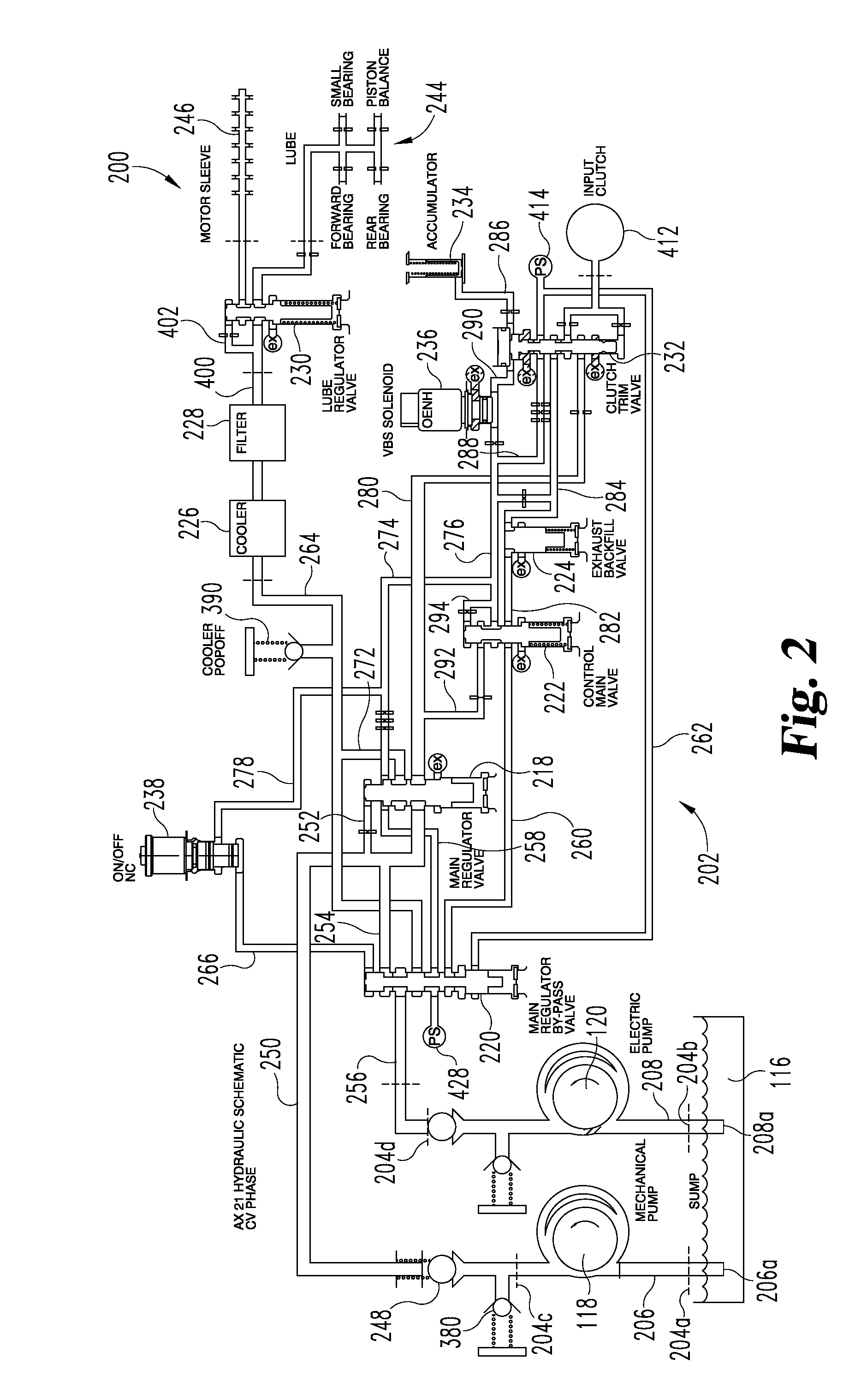
A hydraulic system for a hybrid module which is located between an engine and a transmission includes a parallel arrangement of a mechanical pump and an electric pump. Each pump is constructed and arranged to deliver oil to other portions of the hydraulic system depending on the operational mode. Three operational modes are described including an electric mode, a transition mode, and a cruise mode. Various monitoring and control features are incorporated into the hydraulic system.

Description

CROSS REFERENCE TO RELATED APPLICATION[0001]This application is a continuation of PCT Application No. PCT / US2012 / 025451, filed Feb. 16, 2012, which claims the benefit of U.S. Patent Application Ser. No. 61 / 443,750 filed Feb. 17, 2011, both of which are hereby incorporated by reference.BACKGROUND OF THE INVENTION[0002]With the growing concern over global climate change as well as oil supplies, there has been a recent trend to develop various hybrid systems for motor vehicles. While numerous hybrid systems have been proposed, the systems typically require significant modifications to the drive trains of the vehicles. These modifications make it difficult to retrofit the systems to existing vehicles. Moreover, some of these systems have a tendency to cause significant power loss, which in turn hurts the fuel economy for the vehicle. Thus, there is a need for improvement in this field.[0003]One of the areas for improvement is in the construction and arrangement of the hydraulic system. ...

Claims


Application Information

Patent Timeline
IPC IPC(8): B60K6/12
CPCB60K6/48F16H61/0021F16H61/0031Y02T10/6221B60Y2200/92Y10S903/902B60K6/20Y10S903/903F16H61/0206B60K6/12F16D25/14Y02T10/62Y10S903/915Y10T137/8593Y10T137/85986Y10T137/86131B60W10/30B60W20/00B60K6/36F16H61/0025F16H2061/0037F16K31/0644G05D7/0652
Inventor LONG, CHARLES F.TAYLOR, CHARLES T.
Owner ALLISON TRANSMISSION INC
Why Eureka
Eureka Blog
Learn More