Rotary planing tool

a technology of rotary planing and cutting tools, which is applied in the direction of milling cutters, mechanical surface treatment, milling equipment, etc., can solve the problems of machine losing control, difficulty in obtaining a very smooth surface, and using any guide or template,

Inactive Publication Date: 2013-05-16
ARBORTECH IND
View PDF10 Cites 5 Cited by
  • Summary
  • Abstract
  • Description
  • Claims
  • Application Information

AI Technical Summary

Benefits of technology

[0028]It is particularly preferred in this alternative embodiment that the radially extending blade is removable from the disk. It may be secured thereto by a screw, which may be centrally located in the true circular disk. Central location allows rotation of the blade to a fresh sharp edge, when the blade blunts in a particular portion, and replacement when the blade is completely blunt. The blade may have a concave radial leading surface.
[0029]The invention provides a radical departure from hitherto known freehand wood shaping blades which cut at their perimeter, giving rise to some unexpected advantages.

Problems solved by technology

They remove wood rapidly at any contact with a surface of wood and therefore it is very difficult obtain a very smooth surface or use any guide or template.
They are particularly hazardous in the tight space or corner where teeth on the perimeter can bite into the wood causing the machine to lose control or kick back.

Method used


Image

  • Rotary planing tool
  • Rotary planing tool
  • Rotary planing tool

Examples


Embodiment Construction

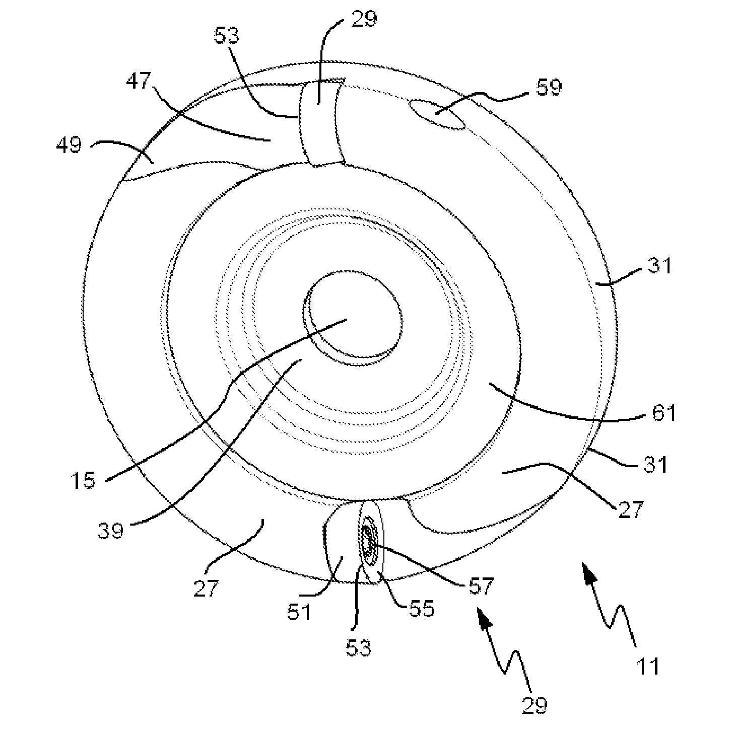
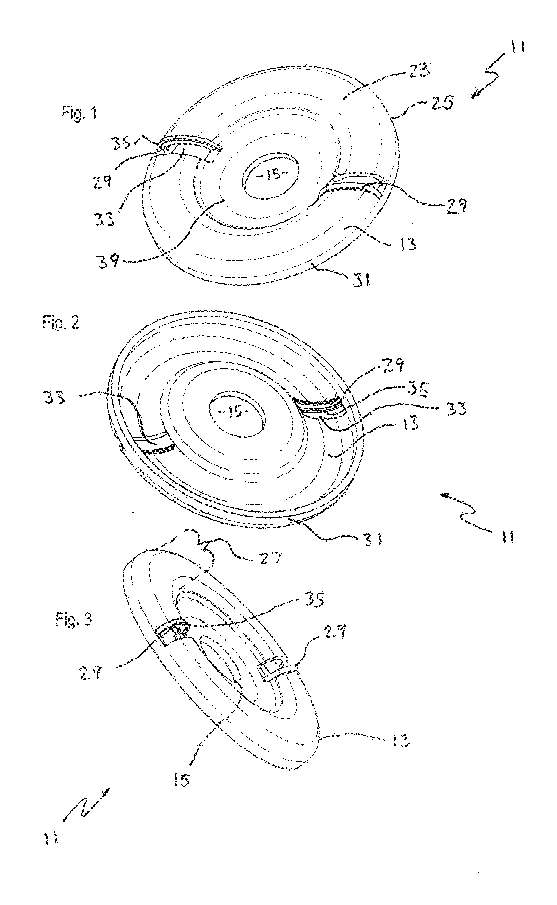
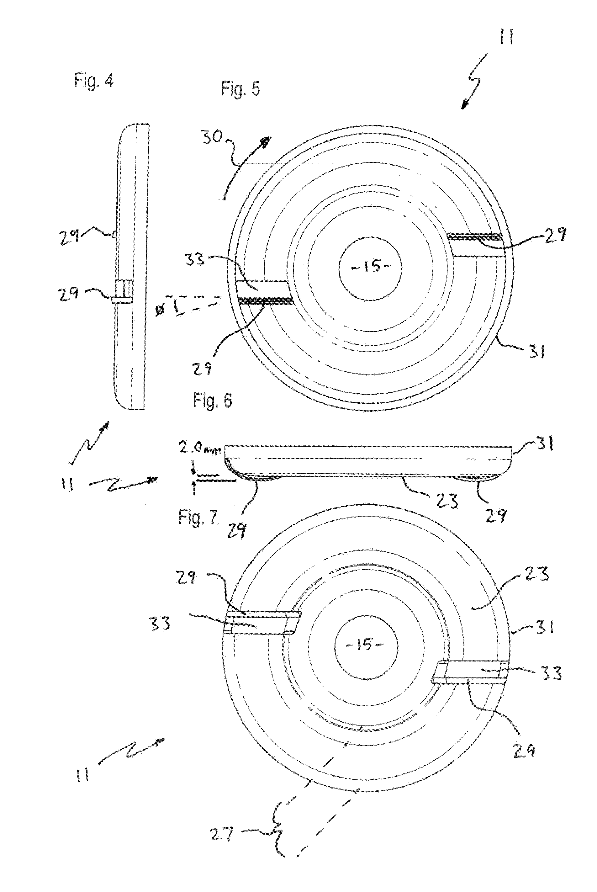
[0074]The first, second and third embodiments are rotary planing tools 11 for planing wood or the like.

[0075]The rotary planing tool 11 is provided in the form of a circular disk 13 which has a central mount in the form of a central circular aperture 15. The central circular aperture 15 is of a diameter which is industry standard so the rotary planing tool 11 can be mounted on a motor in the form of an angle grinder 17. The rotary planing tool 11 is mounted to the spindle 19 of the angle grinder and secured using a fastener 21, as used for grinding disks and cut-off disks in known fashion.

[0076]Shims (not shown) can be provided to adapt the rotary planing tool 11 for mounting on angle grinders having a smaller diameter spindle size. Spacers (also not shown) can be provided if necessary to space the rotary planing tool 11 away from the elevation of the guard fitted to the angle grinder 17, so the rotary planing tool 11 can be laid flat on a workpiece, so that the guard does not inter...


PUM


Abstract

A rotary planing tool comprising a disk having a central mount for mounting on an angle grinder. The rotary planing tool has a working radial surface in which substantially radially extending blades are attached. The working radial surface has radial voids extending before a leading edge of each blade. The blades extend proud of the working radial surface, and each have a curvature tending away from the working radial surface into the circumference of the disk, and are arranged to not extend past the outer circumference of the disk.

Description

CROSS-REFERENCE TO EARLIER APPLICATION[0001]This application is a Continuation-in-Part application from U.S. design patent applications 29 / 421,007, 29 / 421,006 and 29 / 421,008, all filed on May 4, 2012, which claim priority respectively from Australian design applications 15049 / 2011, 15050 / 2011, 15051 / 2011, all filed under a single design application on Nov. 10, 2011, the entireties of which are incorporated by reference herein.TECHNICAL FIELD[0002]This invention relates to a rotary cutting tool, and in particular to a rotary planing tool. This invention has particular application in use as a tool for sculpting objects from wood.BACKGROUND ART[0003]The following discussion of the background art is intended to facilitate an understanding of the present invention only. It should be appreciated that the discussion is not an acknowledgement or admission that any of the material referred to was part of the common general knowledge in any jurisdiction as at the relevant priority dates of th...

Claims


Application Information

Patent Timeline
Patent Type & Authority Applications(United States)
IPC IPC(8): B27G13/10
CPCB27G13/10B23C2210/40B23C5/06B23C5/109B27M1/003B27C1/005B27G13/002B27G13/08B23C5/006
Inventor INKSTER, KEVIN ROSS
Owner ARBORTECH IND
Why Eureka
Try Eureka