Friction stir welding device

a technology of friction stir and welding device, which is applied in the direction of welding device, soldering device, manufacturing tool, etc., can solve the problems of welding error and error generation at the relative position of the workpiece surface with respect to the tool, and achieve the effect of simple configuration

Active Publication Date: 2013-05-16
MITSUBISHI HEAVY IND ENG LTD
View PDF6 Cites 16 Cited by
  • Summary
  • Abstract
  • Description
  • Claims
  • Application Information

AI Technical Summary

Benefits of technology

[0023]According to the friction stir welding device according to the aspects of the present invention, the friction stir welding can be performed by the tool holding unit and the support medium through accurate pressing by the tool, without being influenced by an error generated at the workpieces surface, with a simple configuration.

Problems solved by technology

Here, an error may be generated at a relative position of the workpieces surface with respect to the tool by a board pressure variation due to distortion or a manufacturing error of the workpieces, or a setting error to a surface plate.
When the error is generated at the relative position of the workpieces surface with respect to the tool, a welding force applied to the workpieces from the shoulder surface of the tool is varied, and as a result, a welding error may occur.

Method used


Image

  • Friction stir welding device
  • Friction stir welding device
  • Friction stir welding device

Examples


Embodiment Construction

[0034]Hereinafter, an embodiment according to the present invention will be described with reference to the accompanying drawings.

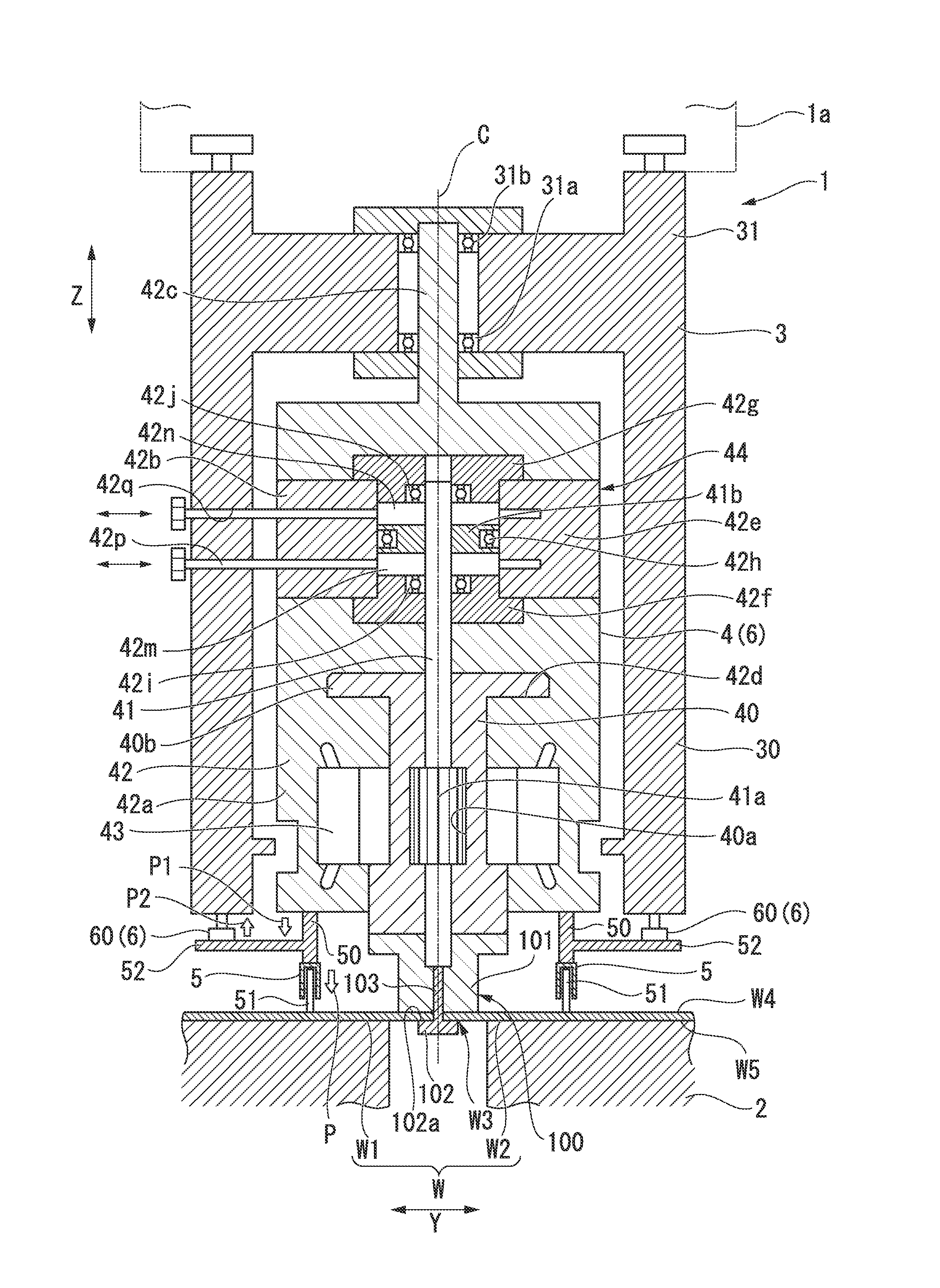
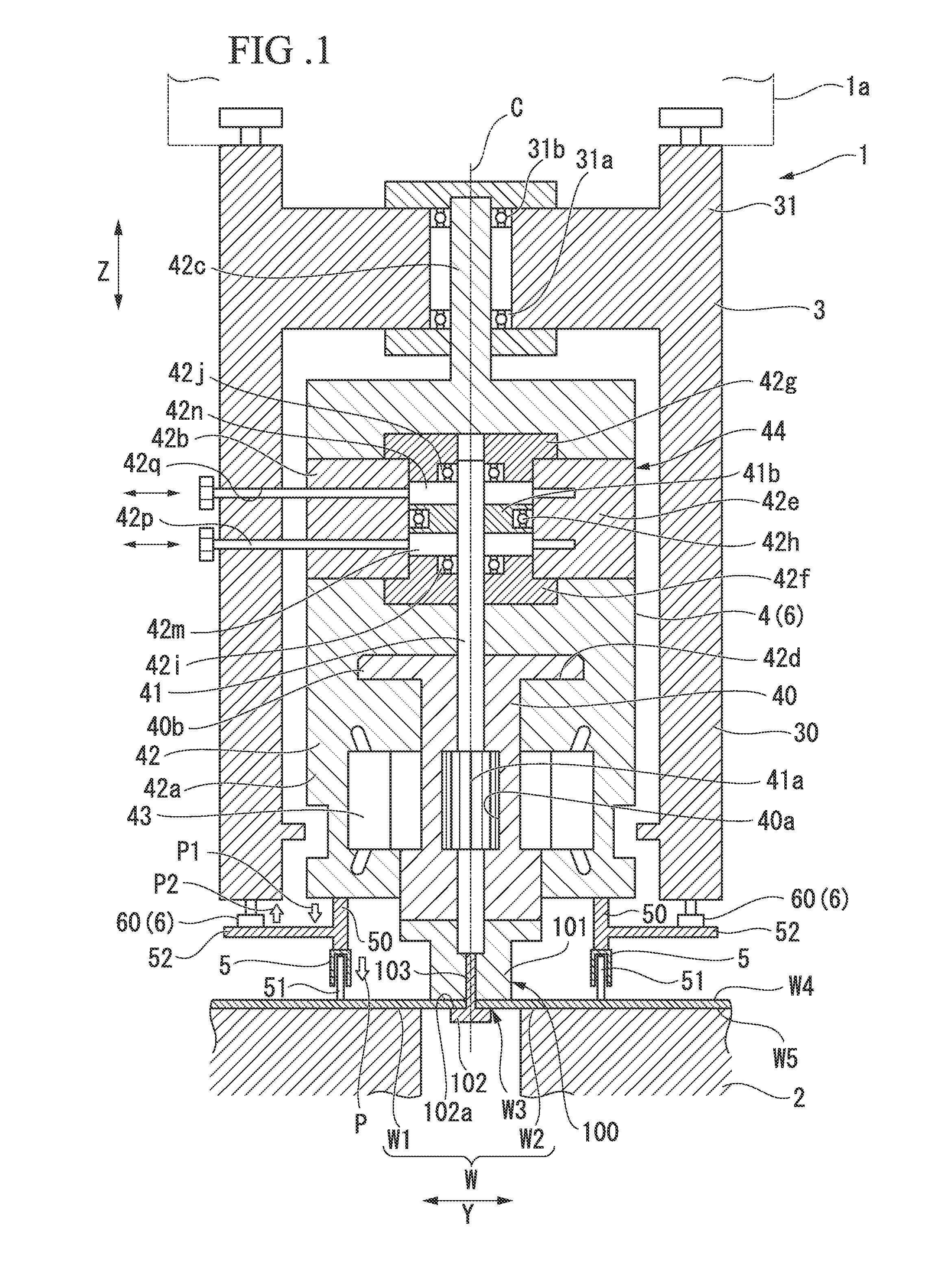
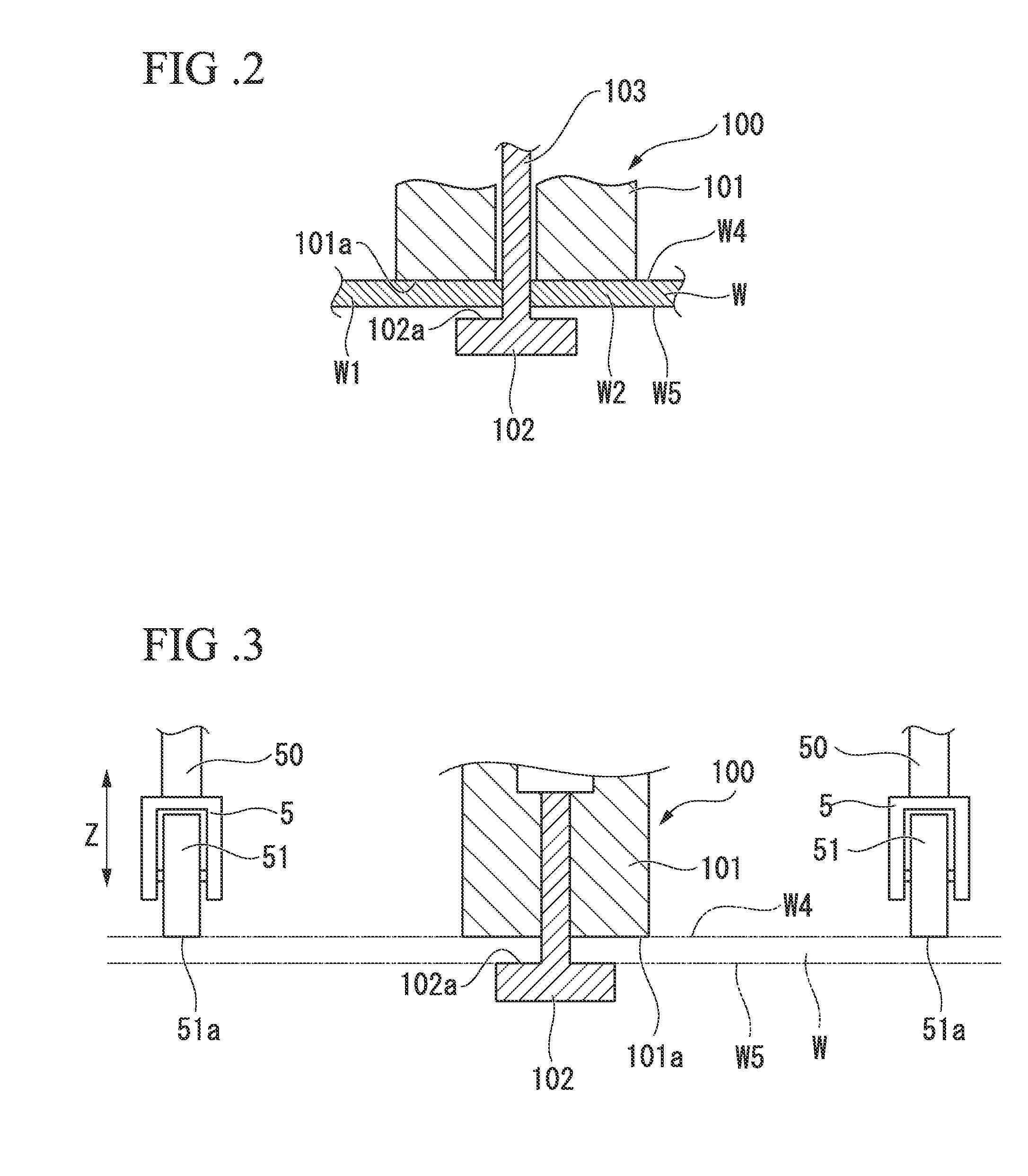
[0035]As shown in FIG. 1, a friction stir welding device 1 of the embodiment is a device for welding workpieces W constituted by a first member W1 and a second member W2 through friction stir welding at a welding place W3 of the first member W1 and the second member W2. The friction stir welding device 1 includes workpieces disposition unit 2 at which the workpieces W are disposed, a main body section 3 disposed over a surface W4 side of the workpieces W disposed at the workpiece disposition unit 2, a tool holding unit 4 installed at the main body section 3 and configured to hold a bobbin tool 100, which is a tool, a support medium 5 configured to support the tool holding unit 4 on the surface W4 of the workpieces W, and a load applying unit 6 configured to apply a preset load to the support medium 5 toward the workpieces W disposed at the workpiece dispo...


PUM

PropertyMeasurementUnit
forceaaaaaaaaaa
weightaaaaaaaaaa
forceaaaaaaaaaa

Abstract

A friction stir welding device (1) includes a workpiece disposition unit (2) at which workpieces (W) is disposed, a main body section (3) disposed at a surface (W4) of the workpieces (W) disposed at the workpiece disposition unit (2), a tool holding unit (4) formed in the main body section (3) to enable advance and retreat in a direction facing the workpieces (Z), which is a direction approaching and separating from the workpieces (W) disposed at the workpiece disposition unit (2), and configured to hold a tool (100), and a support medium (5) formed to satisfy a predetermined relative positional relationship in the direction facing the workpieces (Z) with respect to a first shoulder surface of the tool (100) attached to the tool holding unit (4) and configured to support the tool holding unit (4) on the surface (W4) of the workpieces (W) disposed at the workpieces disposition unit (2).

Description

TECHNICAL FIELD [0001]The present invention relates to a friction stir welding device configured to perform friction stir welding on workpieces.[0002]This application claims priority to and the benefit of Japanese Patent Application No. 2011-033503 filed on Feb. 18, 2011, the disclosure of which is incorporated by reference herein.BACKGROUND ART [0003]One method of welding workpieces constituted by two members is a method referred to as friction stir welding. The friction stir welding is a method of generating frictional heat at workpieces surface by rotating a tool at a welding place of the workpieces in a state in which a predetermined welding pressure is applied to a surface, which is referred to as a shoulder surface of the tool, and softening and welding the workpieces by the frictional heat. The friction stir welding may include a method of using a tool, which is referred to as a bobbin tool type.[0004]The bobbin tool-type tool has a surface side shoulder having one shoulder s...

Claims


Application Information

Patent Timeline
Patent Type & Authority Applications(United States)
IPC IPC(8): B23K20/12
CPCB23K20/1255B23K20/126
Inventor KATO, YOSHINORIFURUTATE, SATOSHIKINOSHITA, TOSHIYUKI
Owner MITSUBISHI HEAVY IND ENG LTD
Why Eureka
Try Eureka