

Lead equipped with means for blocking the extensible cord
Active Publication Date: 2013-05-16
FERPLAST
View PDF4 Cites 5 Cited by
- Summary
- Abstract
- Description
- Claims
- Application Information
AI Technical Summary
Benefits of technology
This patent proposes a pet lead with a winding device for an extended cord and a safety blocking mechanism. The lead is designed to be easy to use and eliminate safety concerns associated with traditional leads. The main technical advantage is the winding device with safety blocking means, which is simple and practical to operate.
Problems solved by technology
The safety pushbutton on traditional lead winding devices presents a series of problems, however, making it difficult to use since it is usually positioned beside the temporary pushbutton.
It also involves construction problems due to the presence of auxiliary mechanical components alongside the main mechanical device.
Method used
View moreImage
Smart ImageViewing Examples

Examples
first embodiment
[0026]FIGS. 5 and 6 represent schematic views showing the first version of the blocking device with a standard tooth;
[0027]FIGS. 7 and 8 represent schematic views showing the second version of the perpendicular rack blocking device;
fourth embodiment
[0029]FIGS. 11 and 12 are schematic views showing a fourth embodiment with a double gear type blocking device;
Login to View More PUM
 Abstract
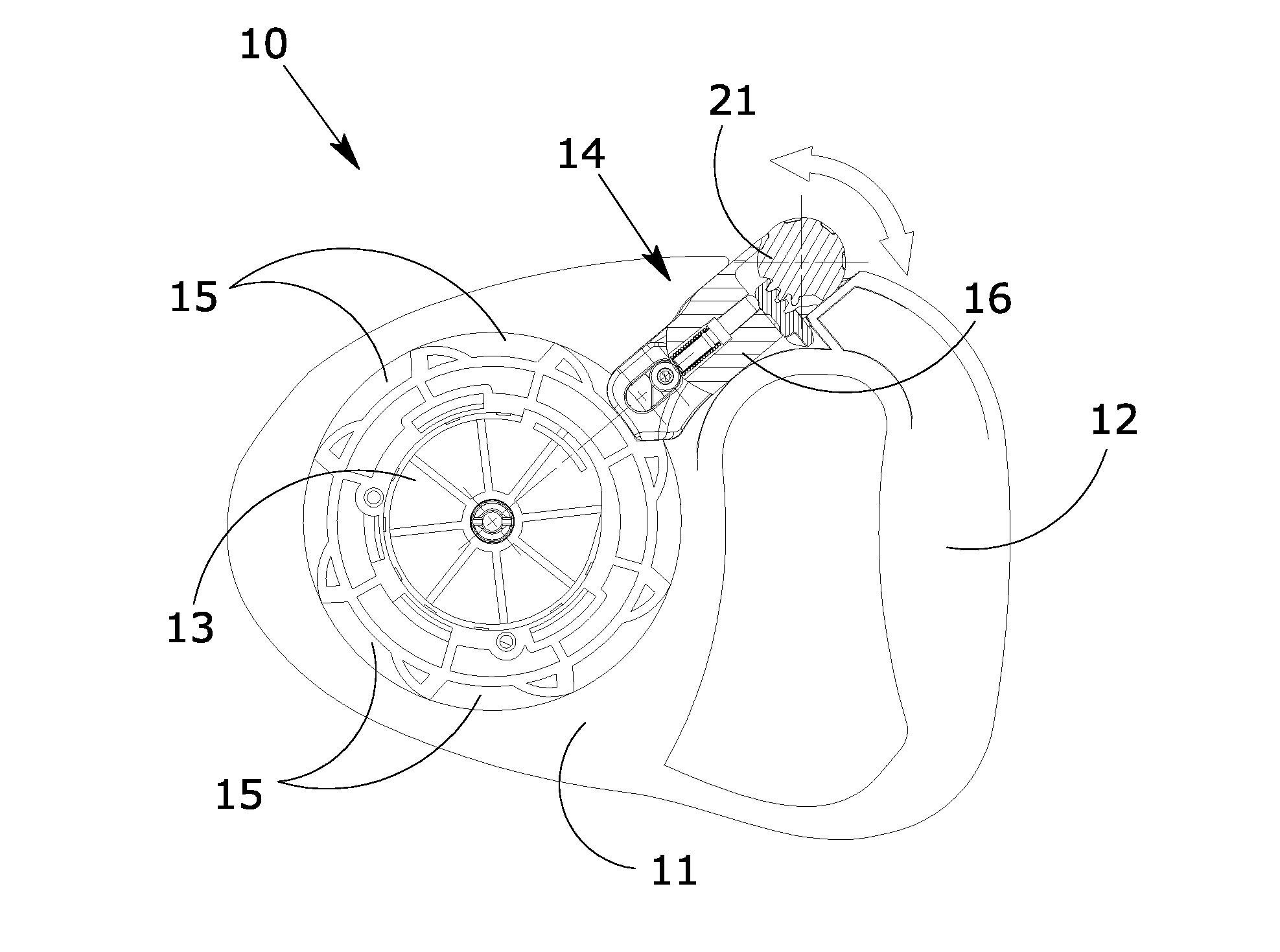
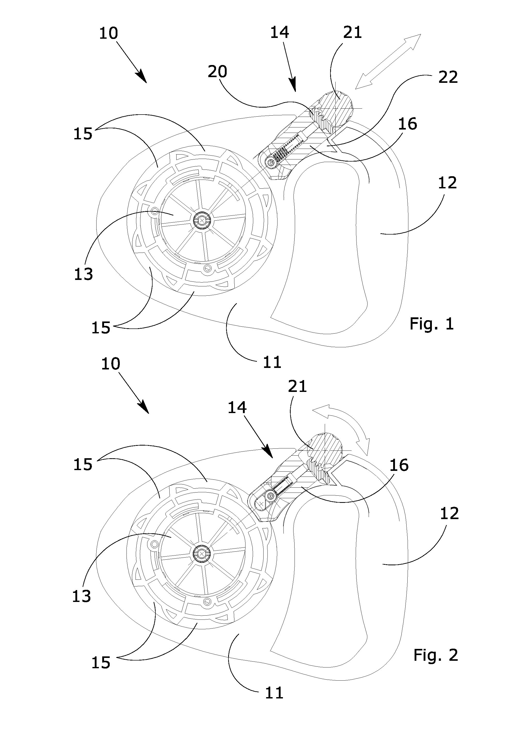
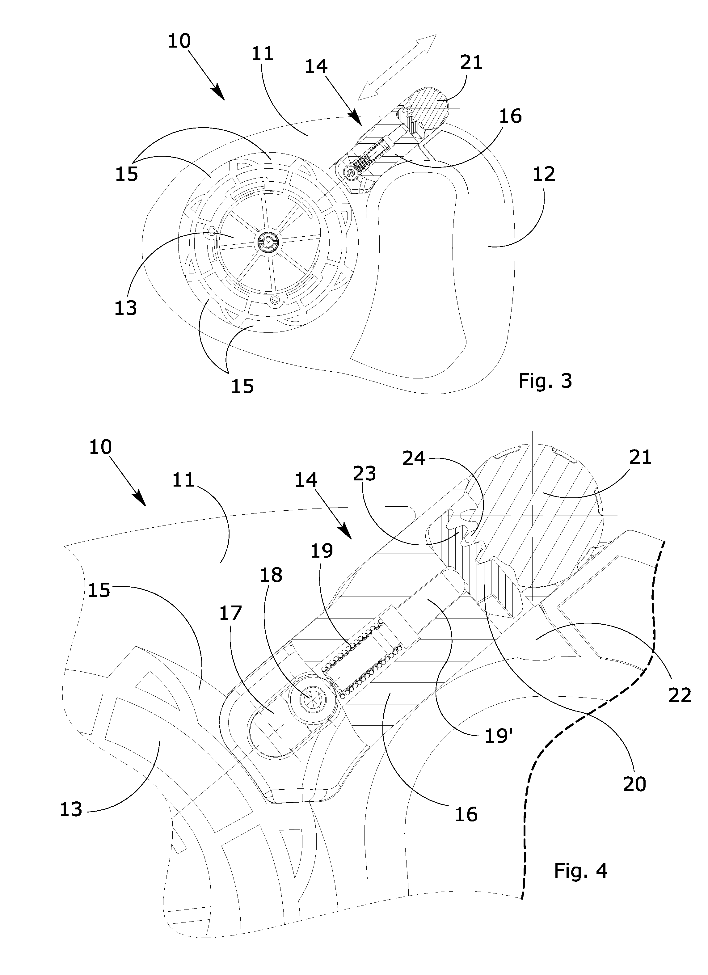
An extensible cord lead comprising a casing (11) containing a winding wheel (13) equipped with housings (15) intercepted by a pushbutton (16) to allow the partial or total blocking of the cord, the pushbutton (16) being equipped with a forward position blocking device consisting of a cursor (20) which slides or rotates in a transverse direction with respect to the axis of the pushbutton (16) in which it is inserted, said cursor (20) being activated by a thumb-turn (21) located on the head of the pushbutton (16), said cursor (20) being able to move from a blocked position to free sliding of the pushbutton, entering and exiting transversally to the sliding axis of the pushbutton (16), in a housing (22) in the boxlike casing (11) of the winding device.
Description
TECHNICAL FIELD[0001]This invention concerns a lead equipped with a wheel winding device for an extensible cord, made in such a way as to allow perfect and easy control of the automated device and blocking of the automatic winder in the required position.[0002]The wheel cord-winding device according to the invention foresees the use of a blocking device which, unlike currently known blocking devices, comprises a safety stop element positioned directly on the pushbutton. This makes it possible on one hand to improve the manoeuvrability of the device by the user and, on the other hand, to simplify the production and assembly of the various components, providing important practical and economic advantages.[0003]The winding device for extensible leads according to the invention is constructed in such a way as to combine the concepts of ergonomics and easy use in a single product.[0004]This invention can be applied in the pet accessory sector, in particular in the sector of accessories s...
Claims
Login to View More Application Information
Patent Timeline
 IPC IPC(8): B65H75/30
CPCA01K27/004
InventorVACCARI, CARLO
OwnerFERPLAST