Drive assist device

a technology of driving assistance and assist device, which is applied in the direction of color television, transportation and packaging, television systems, etc., can solve the problems of difficult use of guidance indicators based on the minimum rotation radius during driving, and frequent change of steering angle,

a technology of driving assistance and assist device, which is applied in the direction of color television, transportation and packaging, television systems, etc., can solve the problems of difficult use of guidance indicators based on the minimum rotation radius during driving, and frequent change of steering angle,

US20130120578A1Active Publication Date: 2013-05-16AISIN SEIKI KK

Image

  • Drive assist device
  • Drive assist device
  • Drive assist device

Examples


Embodiment Construction

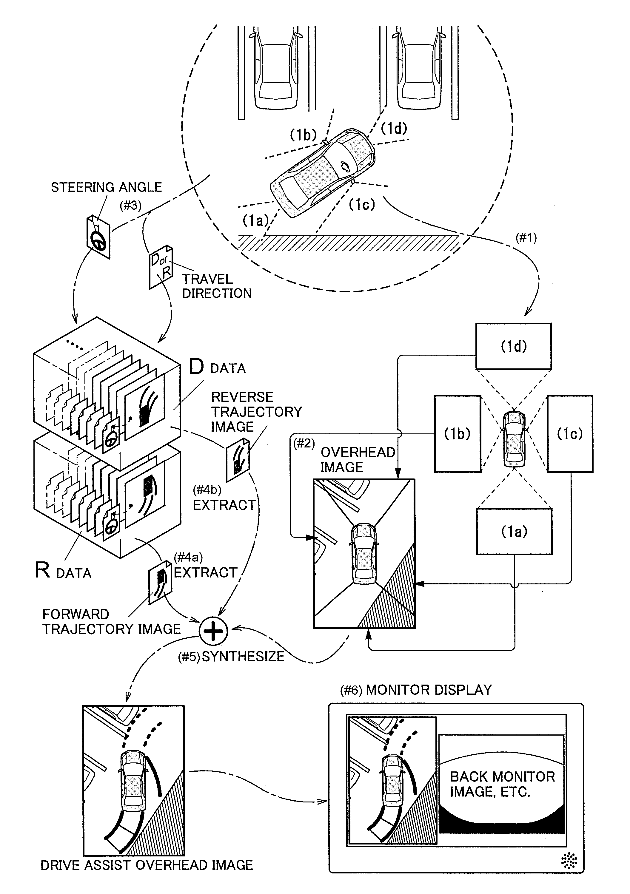
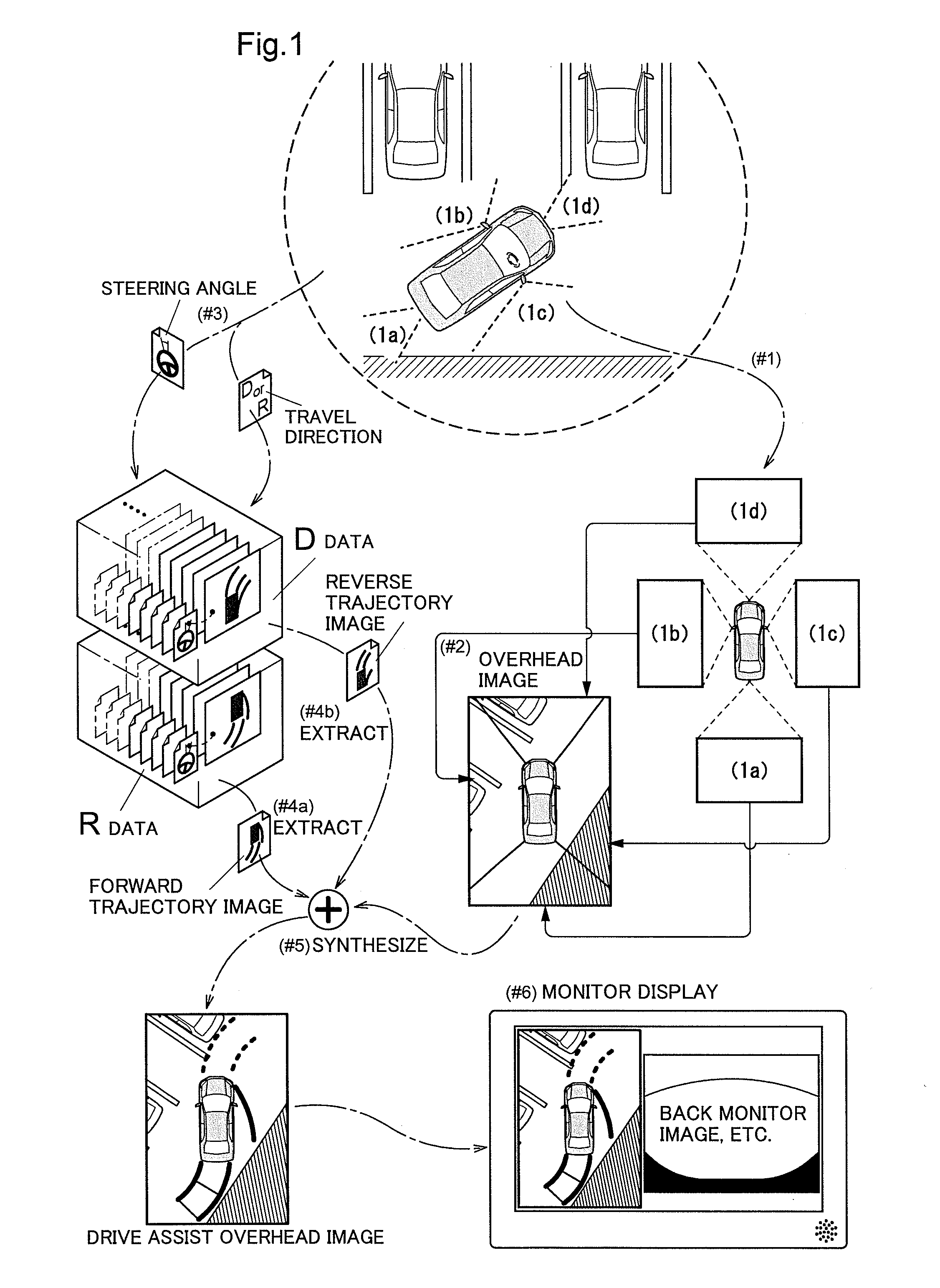
[0021]First, the schematic diagram shown in FIG. 1 will be used to describe principles of generating a drive assist overhead image in which expected trajectory lines of end portions of a vehicle are incorporated into a vehicle periphery overhead image (often called simply an ā€œoverhead imageā€ hereinafter) based on captured images, as used in a drive assist device according to the present invention. This example describes a situation in which a vehicle is turning left while backing out of a perpendicular parking space. The vehicle periphery is covered essentially without gaps by four captured images, indicated as (1a), (1b), (1c), and (1d), captured by vehicle-mounted cameras.

[0022]Drive assistance is commenced when the vehicle advances from a parking area such as a parking lot. First, the four captured images of the surrounding areas that enclose the vehicle are obtained by the vehicle-mounted cameras (#1). The obtained captured images are converted into an overhead image seen from a...


PUM


Abstract

A drive assist device includes: a overhead image generating unit that generates a vehicle periphery overhead image; a forward trajectory setting unit that sets a forward trajectory serving as an expected trajectory in the travel direction of the vehicle occurring when the turning based on a calculated steering angle; a reverse trajectory setting unit that sets a reverse trajectory serving as an expected trajectory in the travel direction of the vehicle or in the opposite direction as the travel direction of the vehicle occurring when turning based on a steering angle in the opposite direction as the calculated steering angle; and a image synthesizing unit that generates a drive assist overhead image for display in a monitor by synthesizing the forward trajectory and the reverse trajectory with the vehicle periphery overhead image.

Description

TECHNICAL FIELD[0001]The present invention relates to drive assistance when turning in areas where there is a high likelihood of contact with an obstruction, such as in a parking lot.BACKGROUND ART[0002]Patent Document 1 discloses a drive assist device that guides a parking operation when attempting to parallel park in a parking space aligned with an access road or when attempting to park perpendicularly. With this drive assist device, the vehicle periphery is captured by cameras installed in multiple positions on the vehicle, an overhead image is created by converting and synthesizing the captured image signals into an image signal whose point of view takes the camera optical axis as perpendicular to the road surface, a guidance indicator is set based on the current position of the vehicle in the overhead image, a superimposed image in which the guidance indicator is overlaid on the overhead image is created, and the superimposed image is displayed in a display means. At this time,...

Claims


Application Information

Patent Timeline
16 May 2013
Publication
US20130120578A1
IPC
H04N7/18
CPC
B60R1/00; B60R2300/607; B62D15/0275; B62D15/0295; H04N7/18; B60R2300/806; B60R1/27
Inventors
IGA, HARUKA; TANAKA, YU