Methods, Apparatus, and Computer-Readable Storage Media for Blended Rendering of Focused Plenoptic Camera Data

a technology blended rendering, which is applied in the field of methods, apparatus and computer-readable storage media for blended rendering of focused plenoptic camera data, can solve the problems of low resolution and relatively low resolution of images rendered from data captured using conventional plenoptic camera, and achieve the effect of higher resolution

Active Publication Date: 2013-05-16
ADOBE SYST INC
View PDF2 Cites 223 Cited by
  • Summary
  • Abstract
  • Description
  • Claims
  • Application Information

AI Technical Summary

Benefits of technology

[0004]Various embodiments of methods, apparatus, and computer-readable storage media for rendering focused plenoptic camera data are described. Focused plenoptic camera technology, in combination with full resolution light-field rendering techniques as described herein, can produce final images at significantly higher resolution than can be rendered from light-field images captured with conventional plenoptic camera technology. Rendering techniques are described that include a rendering with blending technique, and a combined depth-based rendering and rendering with blending technique.

Problems solved by technology

However, images rendered from data captured using conventional plenoptic cameras are of relatively low resolution.
As a result, only a single pixel in the final image is rendered from each microlens image, resulting in low resolution.

Method used


Image

  • Methods, Apparatus, and Computer-Readable Storage Media for Blended Rendering of Focused Plenoptic Camera Data
  • Methods, Apparatus, and Computer-Readable Storage Media for Blended Rendering of Focused Plenoptic Camera Data
  • Methods, Apparatus, and Computer-Readable Storage Media for Blended Rendering of Focused Plenoptic Camera Data

Examples


example depth

-Based Rendering Algorithm

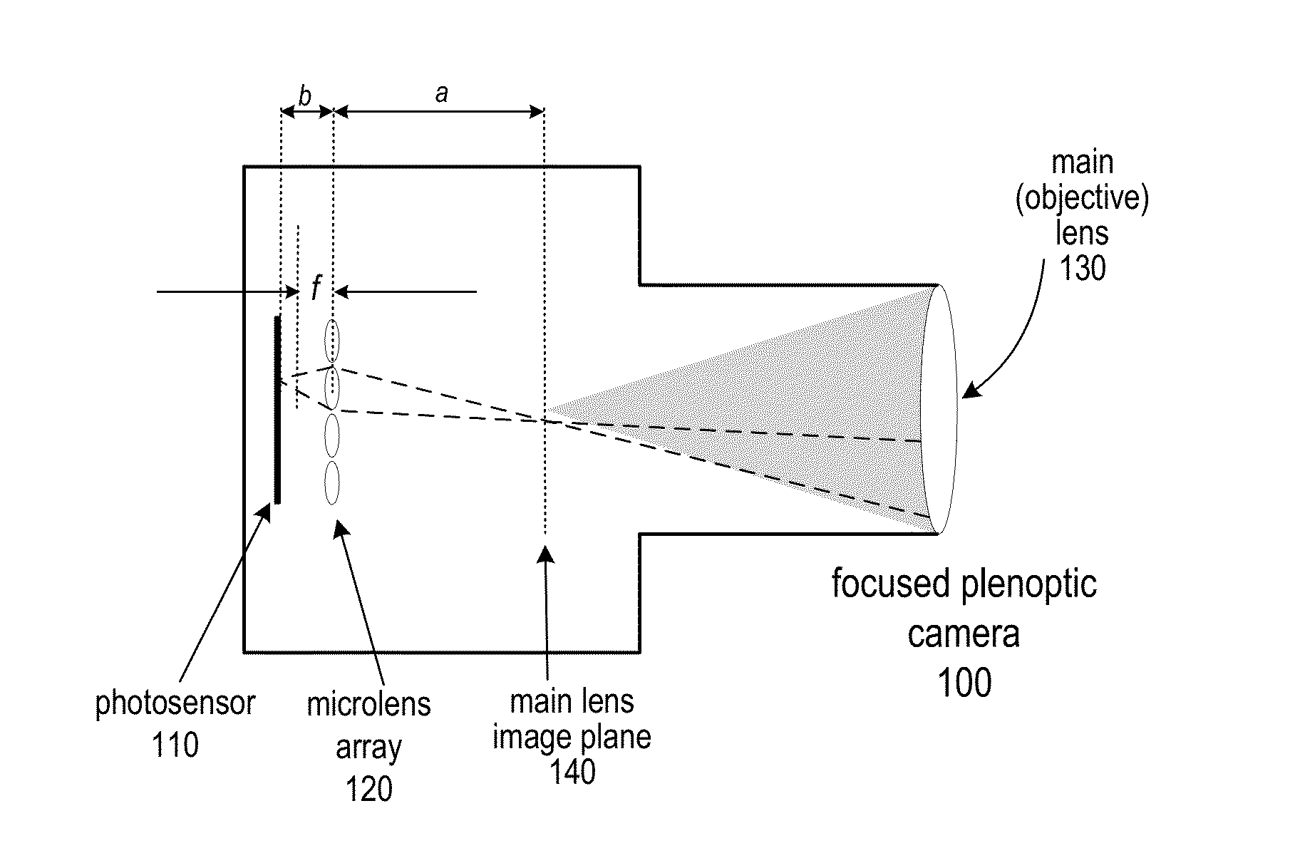
[0096]In at least some embodiments, to render the final image using depth information, the basic rendering algorithm that was previously described may be modified so that, rather than using a fixed pitch value, the value for the given microlens is looked up in the pitch array. In at least some embodiments, the depth-based rendering algorithm may be performed at least in part on parallel computing architectures, for example the architectures of GPU platforms, multi-core or multi-processor platforms, and so on. An example GLSL implementation of the depth-based rendering algorithm that may be used in at least some embodiments is given below. Note that this code renders one point in the output image, and may be performed in parallel to render multiple points in the output image simultaneously. Note that this code is given as an example, and is not intended to be limiting. Any suitable GPU programming language and tools may be used to implement embodiments of th...

example rendering

with Blending Algorithm

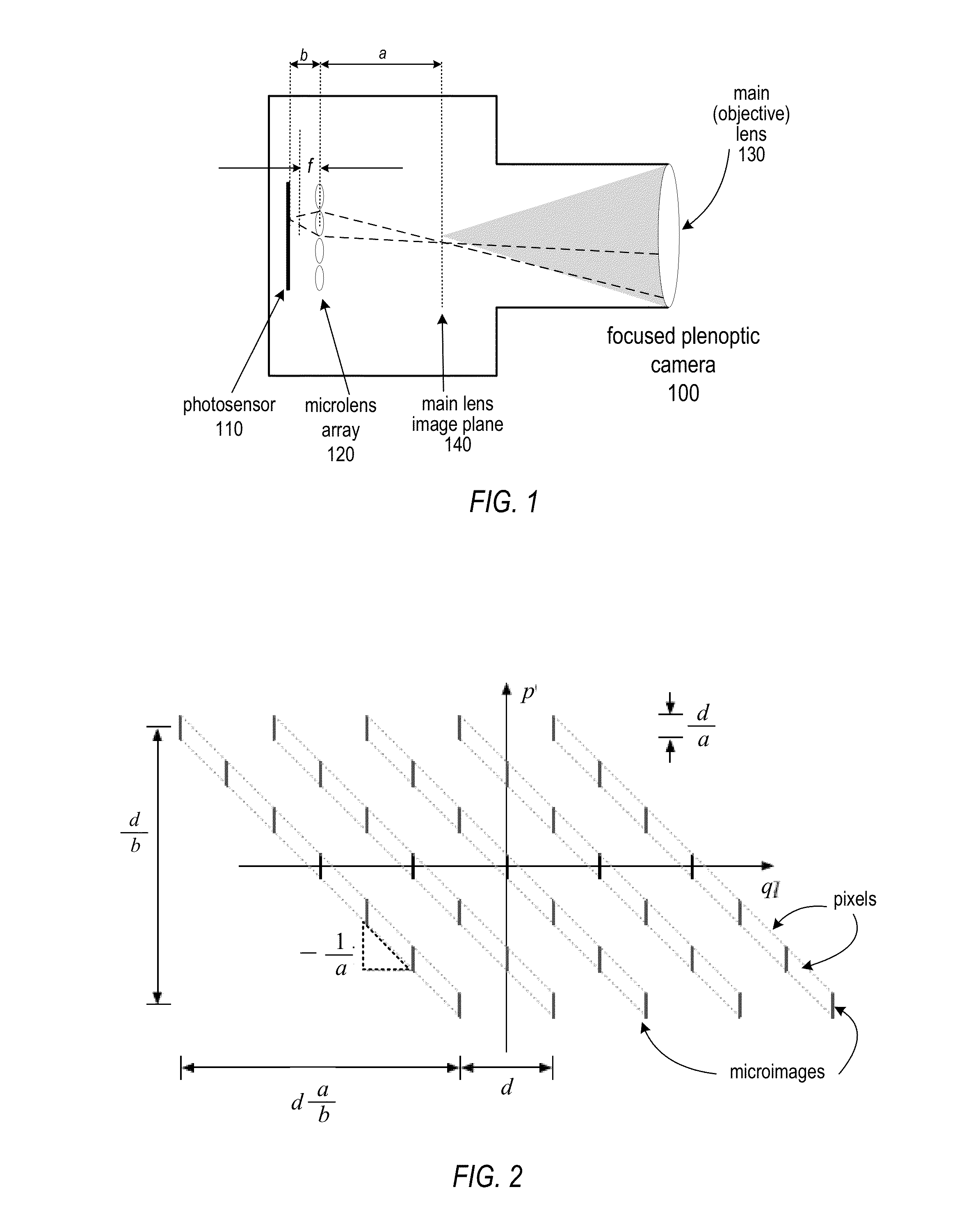
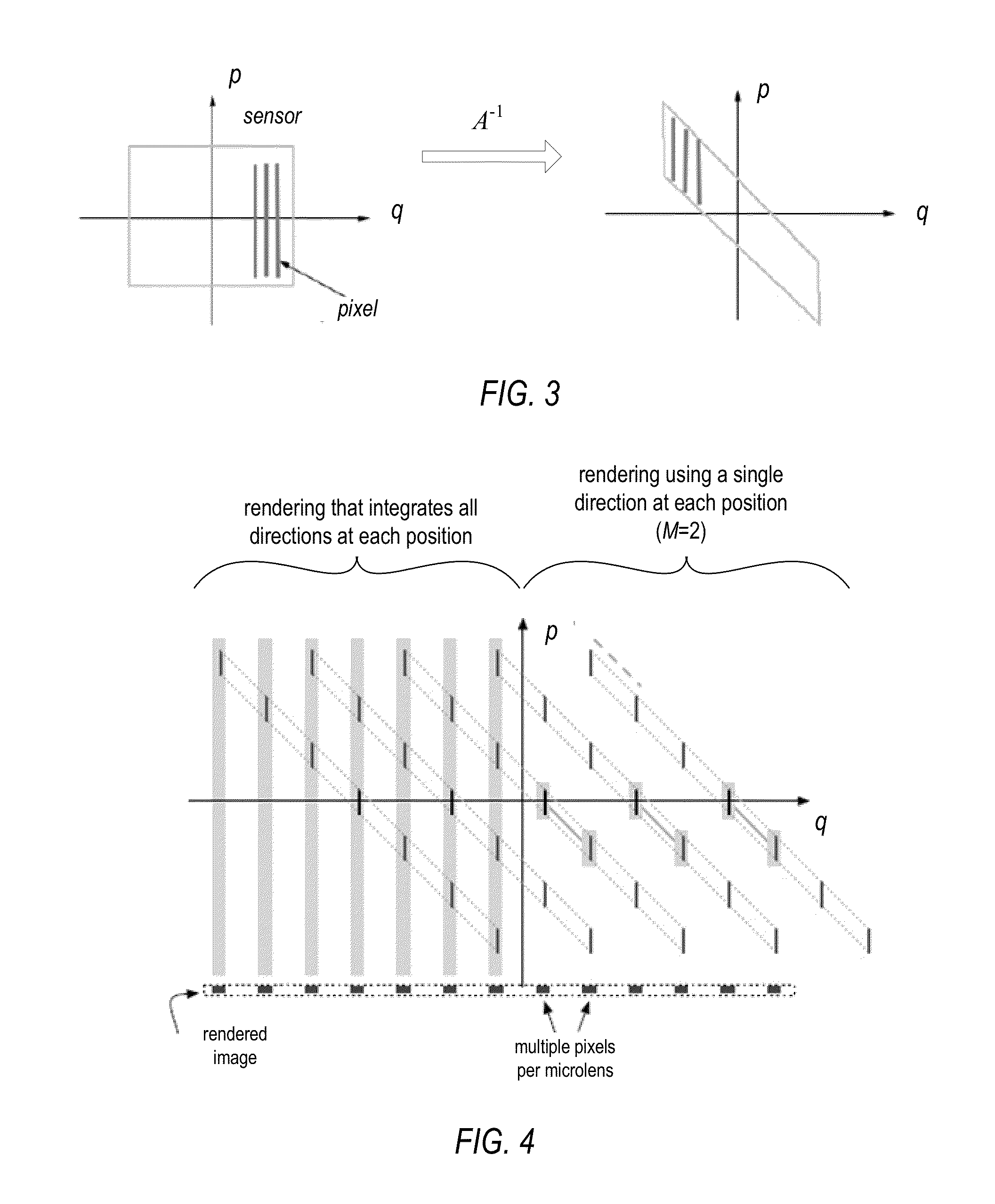
[0108]To realize the integration over p in equation (4), i.e., over multiple views, the same spatial point may be averaged together (blended) across microlens images. For microlenses spaced μ apart and a patch size of M, the pixels that need to be averaged together to render a given pixel in the rendered image will be distance (μ−M) apart. That is, all pixels at position f(x) are averaged, where:

fi(x)=pi+q′where(F1)pi=⌊xμ⌋+i(μ-M)(F2)

for i= . . . , −2, −1, 0, 1, 2, . . . and q′ is given by equation (C3):

q′=q+μ-M2=(xμ-p)M+μ-M2.(C3)

[0109]Since μ is constant, this means that for images generated with a given sampling pitch M there is a fixed upper bound, Um, for the absolute value of i, namely

lim=(⌊μM⌋-12)(F3)

[0110]In addition, in at least some embodiments the contribution from different views may be weighted to perform weighted blending. To accomplish weighted blending within GLSL implementations, another texture (single-component, in this case) may be as a looku...

example implementations

of Rendering Methods

[0119]Embodiments of the full-resolution rendering techniques as described herein may be performed by a rendering module implemented by program instructions stored in a computer-readable storage medium and executable by one or more processors (e.g., one or more CPUs or GPUs) of a computer system or other device. FIG. 21 illustrates a full-resolution rendering module rendering images from a flat captured, for example, by various embodiments of a focused plenoptic camera. Rendering module 920 may, for example, implement a basic full resolution rendering technique, a depth-based rendering technique, a rendering with blending technique, and / or a combined depth-based rendering and rendering with blending technique for rendering full-resolution images from flats captured using focused plenoptic cameras, as described herein. FIG. 22 illustrates an example computer system on which embodiments of rendering module 920 may be implemented. FIG. 20 illustrates an example user...


PUM


Abstract

Methods, apparatus, and computer-readable storage media for rendering focused plenoptic camera data. A rendering with blending technique is described that blends values from positions in multiple microimages and assigns the blended value to a given point in the output image. A rendering technique that combines depth-based rendering and rendering with blending is also described. Depth-based rendering estimates depth at each microimage and then applies that depth to determine a position in the input flat from which to read a value to be assigned to a given point in the output image. The techniques may be implemented according to parallel processing technology that renders multiple points of the output image in parallel. In at least some embodiments, the parallel processing technology is graphical processing unit (GPU) technology.

Description

PRIORITY INFORMATION[0001]This application claims benefit of priority of U.S. Provisional Application Ser. No. 61 / 310,203 entitled “Focused Plenoptic Camera and Rendering” filed Mar. 3, 2010, the content of which is incorporated by reference herein in its entirety.BACKGROUNDDescription of the Related Art[0002]In contrast to conventional cameras, light-field, or radiance capturing, cameras sample the four-dimensional (4-D) optical phase space or light-field, and in doing so capture information about the directional distribution of the light rays. This information captured by light-field cameras may be referred to as the light-field, the plenoptic function, or radiance. In computational photography, a light-field is a 4-D record of all light rays in 3-D. Radiance describes both spatial and angular information, and is defined as density of energy per unit of area per unit of stereo angle (in radians). A light-field camera captures radiance; therefore, light-field images originally take...

Claims


Application Information

Patent Timeline
Patent Type & Authority Applications(United States)
IPC IPC(8): H04N5/228
CPCG06T15/205G06T2200/21
Inventor GEORGIEV, TODOR G.LUMSDAINE, ANDREW
Owner ADOBE SYST INC
Why Eureka
Try Eureka