Optical device and charging system including the same

a charging system and optical device technology, applied in the field of optical devices, can solve the problems of low resolution and inability to properly view 3d images, and achieve the effects of shortening the length of the wiring connection, high efficiency, and improving design

Inactive Publication Date: 2013-05-16
PANASONIC INTELLECTUAL PROPERTY MANAGEMENT CO LTD
View PDF7 Cites 34 Cited by
  • Summary
  • Abstract
  • Description
  • Claims
  • Application Information

AI Technical Summary

Benefits of technology

[0023]According to the optical device of the present invention, since a power receiver coil is provided, non-contact charging of the secondary battery is possible. Therefore, there is no need to provide a terminal for charging on the outside surface of the viewing device, and the design can be easily improved. In addition, since the case of the secondary battery is made of a non-magnetic material, the magnetic field around the receiver coil will not be disturbed even when the secondary battery is disposed in proximity to the receiver coil, and the secondary battery can be charged with high efficiency. This allows the secondary battery and the receiving coil to be arranged more freely.
[0024]As a result, for example, it is possible to arrange the secondary battery and the receiver coil in the same temple, i.e., one of the right and left temples, as closely to each other as possible. This makes it possible to shorten the length of the wiring connecting them to each other. Therefore, failures due to disconnection or the like become unlikely to occur, and a highly reliable optical device can be realized.
[0025]While the novel features of the invention are set forth particularly in the appended claims, the invention, both as to organization and content, will be better understood and appreciated, along with other objects and features thereof, from the following detailed description taken in conjunction with the drawings.

Problems solved by technology

Accordingly, in the passive system, 3D images cannot be properly viewed unless the images are viewed in the vicinity of the front of the display device.
Moreover, since the right-eye and left-eye images are simultaneously displayed on the same screen, the resolution is low.

Method used


Image

  • Optical device and charging system including the same
  • Optical device and charging system including the same
  • Optical device and charging system including the same

Examples


embodiment 1

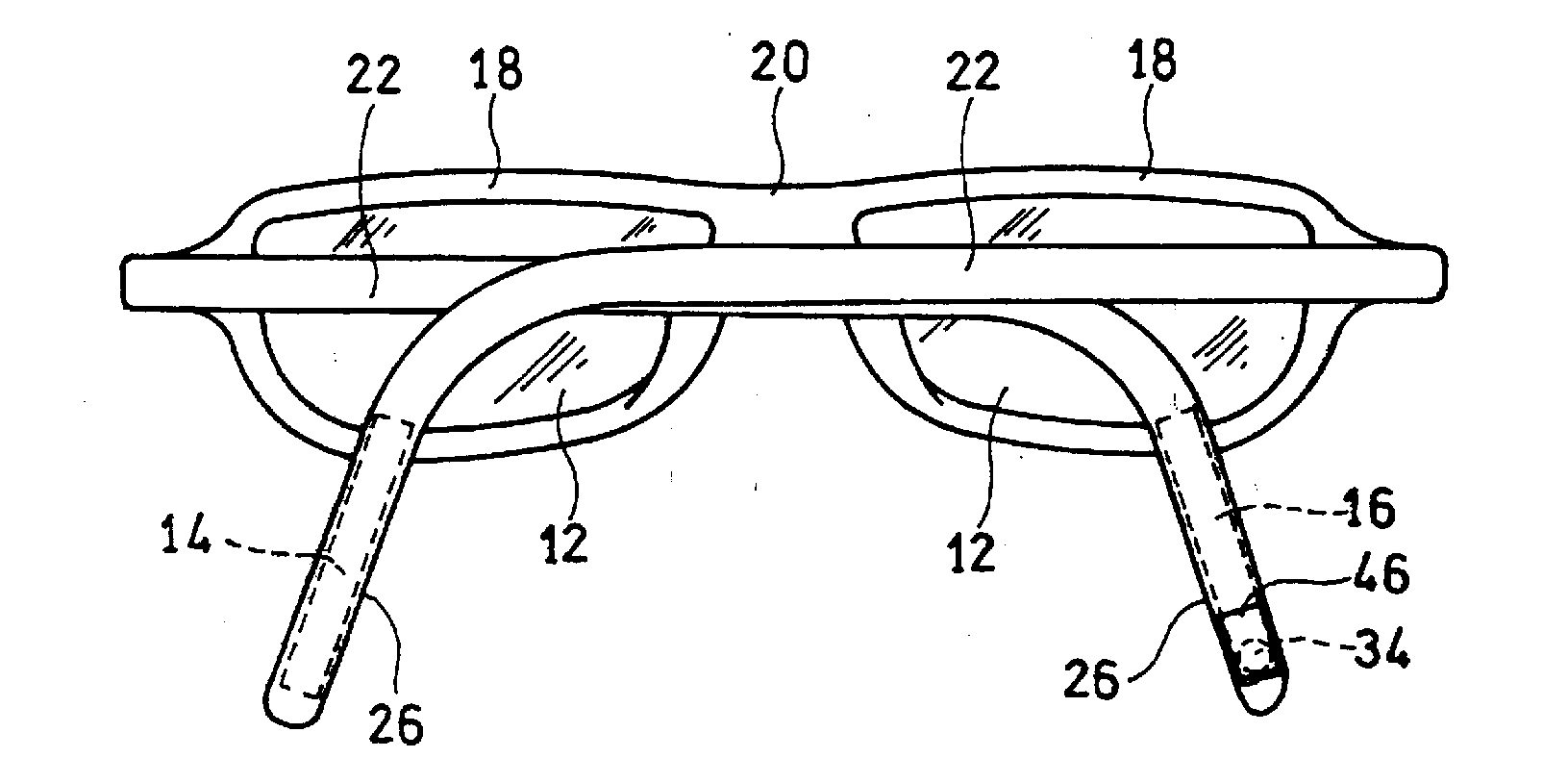
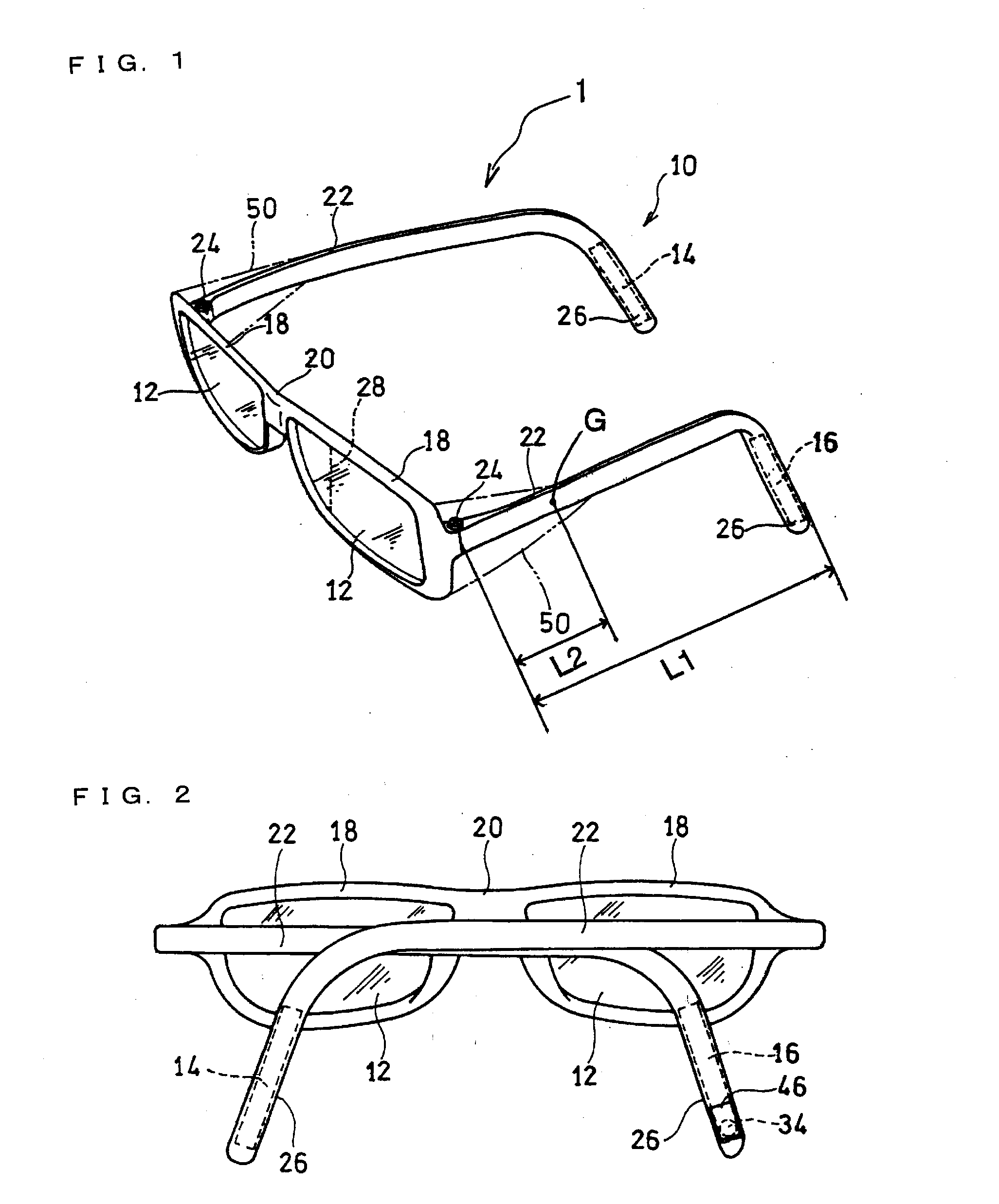
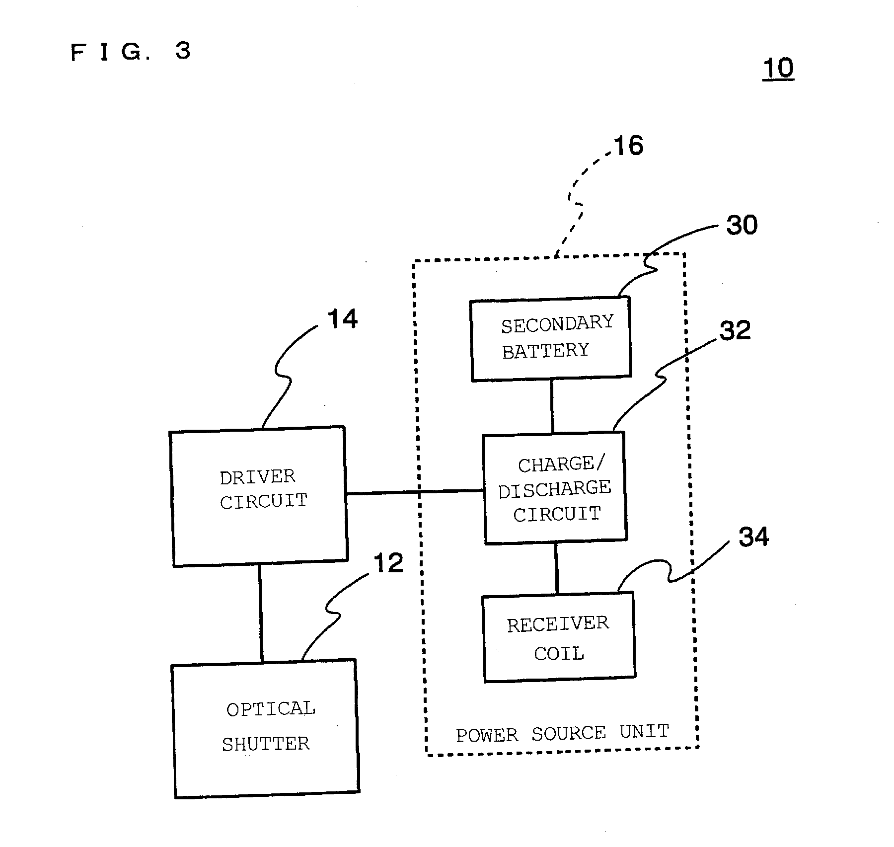
[0067]FIG. 1 is an oblique view of a stereoscopic image viewing device being an optical device according to Embodiment 1 of the present invention. FIG. 2 is a rear view of the viewing device with the temples being folded. FIG. 3 is a functional block diagram of the stereoscopic image viewing device.

[0068]The stereoscopic image viewing device (hereinafter referred to as the “viewing device”) 10 is an eyeglasses-like viewing device compatible with an active-shutter stereoscopic image viewing system.

[0069]The active-shutter stereoscopic image viewing system is a system for viewing stereoscopic images in which right-eye and left-eye images are displayed on a display device such as a 3D television while being alternately switched at high speed, and optical shutters of the viewing device 10 are alternately opened and closed in synchronization with the switching of images on the display device.

[0070]In the viewing device 10, a driver circuit 14 is connected to the electrodes (not shown) of...

embodiment 2

[0130]FIG. 11 illustrates a lens for use in variable focus eyeglasses being an optical device according to Embodiment 2, as viewed from a direction perpendicular to an incident direction of light. The appearance of the variable focus eyeglasses themselves is similar to that of the viewing device in FIG. 1. Therefore, similar portions are denoted by the same reference numerals as in FIG. 1. In addition, the thickness ratio and other ratios among the portions shown in FIG. 11 are changed from the actual ratio for better visibility.

[0131]Lens 70 illustrated in the figure includes a base lens 70a, and a planar electroactive element 71 embedded in the base lens 70a. For example, a normal optical lens (concave lens) for myopia correction can be used as the base lens 70a. The electroactive element 71 is a device having a refractive index that is variable in response to application of electrical energy. The electroactive element 71 is in optical communication with the base lens 70a. The len...

embodiment 3

[0147]FIG. 13 is a side view of a charger 80 used in a charging system according to Embodiment 3. The shape of the charger 80 is similar to that of the charger 40 of FIG. 8 or the charger 40A of FIG. 10. The charger 80 differs from those charges in that the transmitter coil 38 is movable. The charger 80 as illustrated is provided with only one transmitter coil 38, as in the charger 40 of FIG. 8. Alternatively, the charger 80 may be provided with four transmitter coils 38, as in the charger 40A of FIG. 10. In the charger 80 as illustrated, the initial position of the transmitter coil 38 is the same as that of the transmitter coil 38 in the charger 40 of FIG. 8.

[0148]The charger 80 includes a magnetic flux density detector coil 81 for detecting a magnetic flux density (a first magnetic flux density) at a first point around the initial position of the transmitter coil 38, a magnetic flux density detector coil 82 for detecting a magnetic flux density (a second magnetic flux density) at ...


PUM

PropertyMeasurementUnit
widthaaaaaaaaaa
distanceaaaaaaaaaa
lengthaaaaaaaaaa

Abstract

An optical device including: one or more optical components configured to be electrically actuated such that light transmission states are variable, a driver circuit for the optical components, a power source unit for driving the optical components, a pair of rims for supporting the optical components, a pair of temples having front and rear ends and being connected at the front ends to the pair of rims, and a pair of earpieces formed at the rear ends of the pair of temples. The power source unit includes a secondary battery, and a power receiver coil for charging the secondary battery. The secondary battery includes a case made of a non-magnetic material.

Description

TECHNICAL FIELD [0001]The present invention relates to optical devices, more specifically to a technology for improving the convenience of use of a head mounted optical device to be worn on the head of a user.BACKGROUND ART [0002]Some stereoscopic image viewing devices (hereinafter simply referred to as “viewing devices”) generally called 3D eyeglasses or 3D glasses support an active system, and some support a passive system.[0003]The active system is a system in which on a display device such as a television, right-eye and left-eye images are alternately switched and displayed, while on a viewing device, liquid crystal shutters or the like provided on right and left lens portions are alternately opened and closed in synchronization with the switching of images on the display device (see Patent Literatures 1 and 2).[0004]The active system allows viewing stereoscopic image by using a display device having almost the same structure as that of the conventional display device, and simpl...

Claims


Application Information

Patent Timeline
Patent Type & Authority Applications(United States)
IPC IPC(8): G02C7/08G02F1/13G02C11/00
CPCG02B27/2264H04N5/64H04N2213/008G02C7/083G02B2027/0178G02F1/1313H04N13/0438G02B27/017G02C11/10H04N13/341G02B30/24G02B30/00
Inventor KAKINUMA, AKIRAYONEDA, KEISUKEKATO, FUMIO
Owner PANASONIC INTELLECTUAL PROPERTY MANAGEMENT CO LTD
Why Eureka
Try Eureka