Apparatus and method to measure temperature of 3D semiconductor structures via laser diffraction

a technology of laser diffraction and apparatus, which is applied in the direction of optical radiation measurement, pyrometry using electric radation detectors, instruments, etc., can solve the problems of reducing the accuracy of non-contact metrology, the temperature derived by the pyrometer is often inaccurate, and the non-contact metrology is particularly inaccurate when

Inactive Publication Date: 2013-05-16
APPLIED MATERIALS INC
View PDF21 Cites 1 Cited by
  • Summary
  • Abstract
  • Description
  • Claims
  • Application Information

AI Technical Summary

Benefits of technology

The present invention is about a device and method for accurately measuring the temperature of a substrate by measuring the amount of light emitted from it. This is important for determining the energy levels of the substrate and monitoring its health. The device uses a special lens to collect the light from the substrate, which has been scattered due to the surface's 3D features. The lens ensures that almost all the light collected is scattered, resulting in a more accurate measurement of the substrate's emissivity. This increases the accuracy of the temperature measurement compared to traditional methods. The invention can be used for a variety of substrates with 3D features on their surface.

Problems solved by technology

One consequence of 3D features is a reduction in the accuracy of non-contact metrology due to the loss of specular reflection (e.g., when the incident angle of an irradiating light source is equal to the angle of reflection) due to the decreased collection of light by a detector.
However, not all objects have the same emissivity, and therefore, the temperature derived by the pyrometer is frequently inaccurate.
Non-contact metrology is particularly inaccurate when processing 3D structures as compared to planar substrates.
The metrology of 3D structures is even less accurate due to difficulties in determining object emissivity.
Irradiation of a 3D structure results in scattering and interference of light reflected from the substrate, making emissivity determination inaccurate when utilizing conventional emissivity measurement techniques.

Method used


Image

  • Apparatus and method to measure temperature of 3D semiconductor structures via laser diffraction
  • Apparatus and method to measure temperature of 3D semiconductor structures via laser diffraction
  • Apparatus and method to measure temperature of 3D semiconductor structures via laser diffraction

Examples


Embodiment Construction

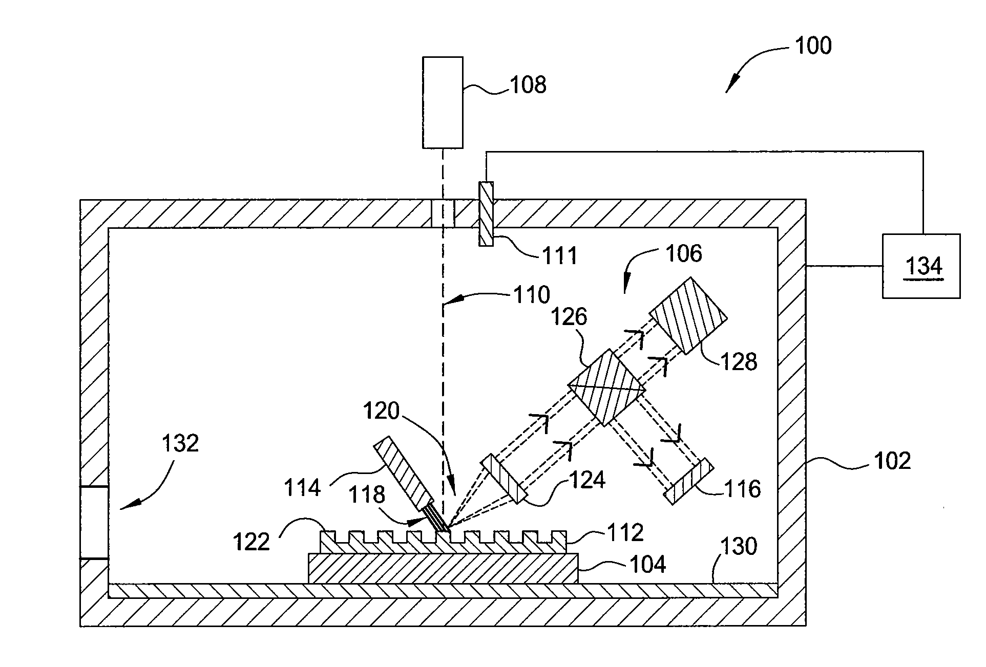
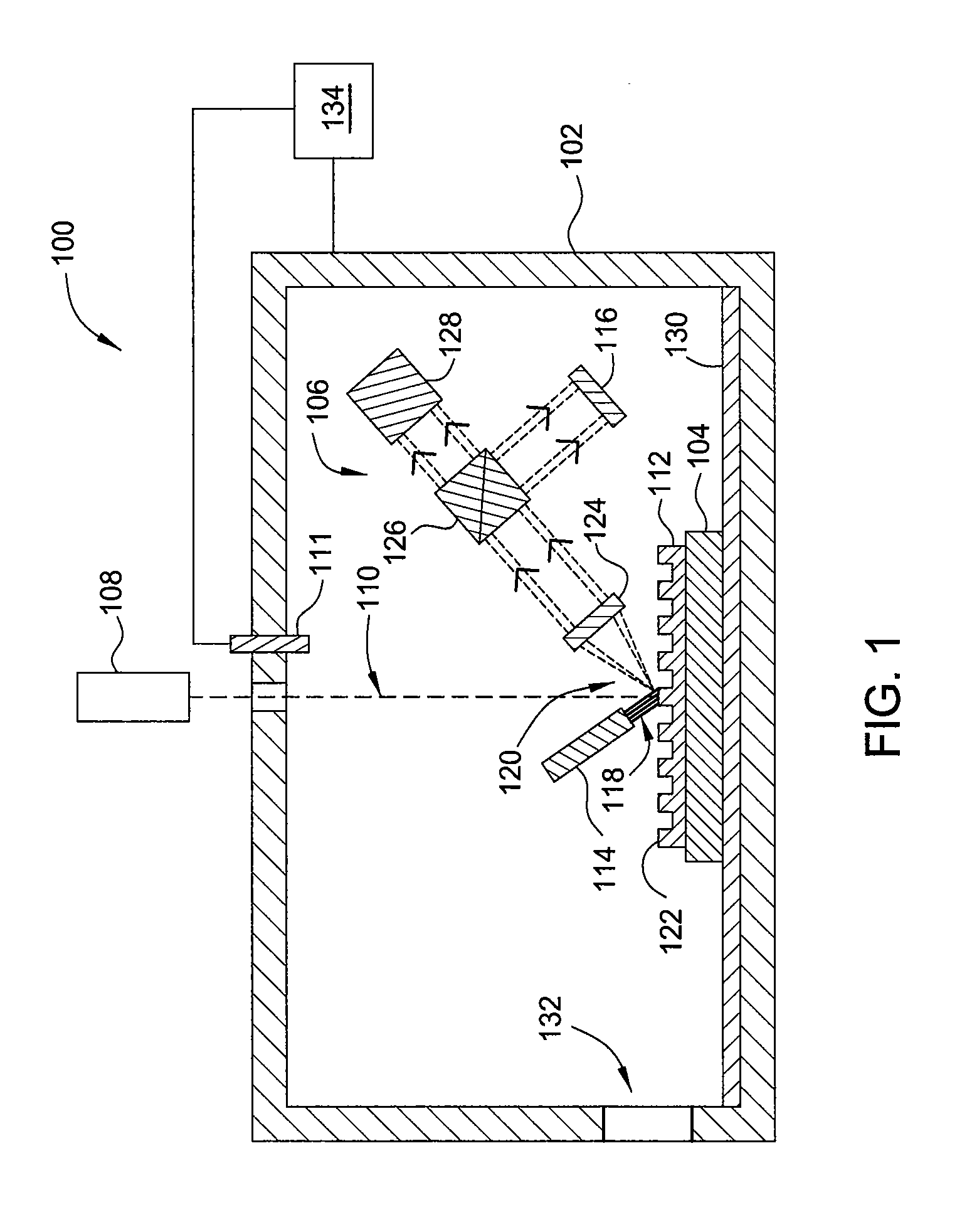
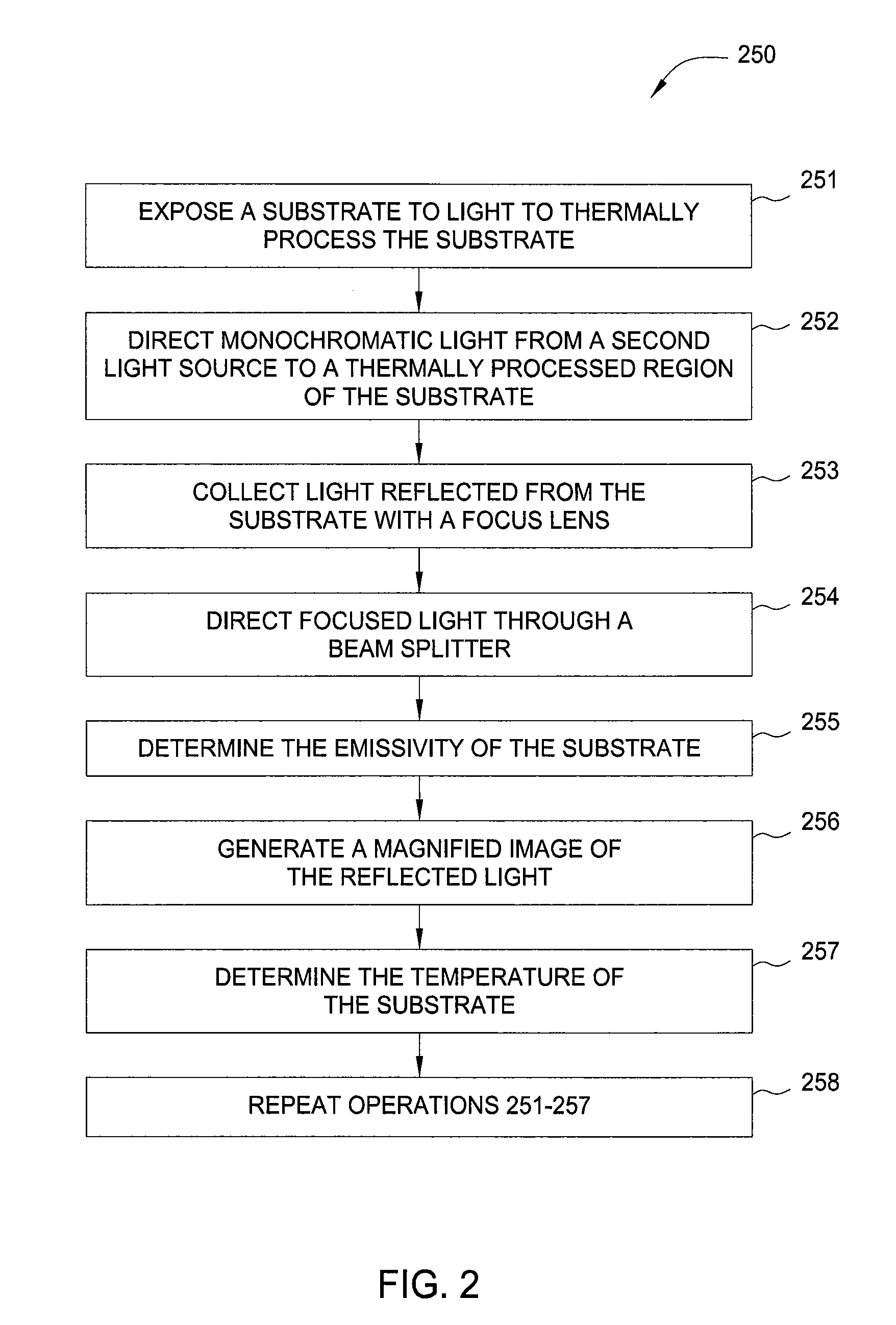
[0018]Embodiments of the present invention generally relate to apparatus for and methods of measuring and monitoring the temperature of a substrate having a 3D feature thereon. The apparatus include a light source for irradiating a substrate having a 3D feature thereon, a focus lens for gathering and focusing light reflected from the substrate, and an emissometer for detecting the emissivity of the focused reflected light. The apparatus may also include a beam splitter to split light reflected from the substrate towards the emissometer as well as an imaging device. The imaging device provides a magnified image of the diffraction pattern of the reflected light. The method includes irradiating a substrate having a 3D feature thereon with light from a light source, reflecting the light off of the substrate, and focusing the reflected light with a focusing lens. The focused light is then directed to a sensor and the emissivity of the substrate is measured. The reflected light may also i...


PUM


Abstract

Embodiments of the present invention generally relate to apparatus for and methods of measuring and monitoring the temperature of a substrate having a 3D feature thereon. The apparatus include a light source for irradiating a substrate having a 3D feature thereon, a focus lens for gathering and focusing reflected light, and an emissometer for detecting the emissivity of the focused reflected light. The apparatus may also include a beam splitter and an imaging device. The imaging device provides a magnified image of the diffraction pattern of the reflected light. The method includes irradiating a substrate having a 3D feature thereon with light, and focusing reflected light with a focusing lens. The focused light is then directed to a sensor and the emissivity of the substrate is measured. The reflected light may also impinge upon an imaging device to generate a magnified image of the diffraction pattern of the reflected light.

Description

CROSS-REFERENCE TO RELATED APPLICATIONS[0001]This application claims benefit of U.S. Provisional Patent Application Ser. No. 61 / 558,309, filed Nov. 10, 2011, which is herein incorporated by reference.BACKGROUND OF THE INVENTION[0002]1. Field of the Invention[0003]Embodiments of the invention generally relate to apparatus and methods for measuring the temperature of substrates having three-dimensional (3D) features thereon.[0004]2. Description of the Related Art[0005]The drive for continued scaling of semiconductor devices results in new architectures for semiconductor devices, including 3D features. One consequence of 3D features is a reduction in the accuracy of non-contact metrology due to the loss of specular reflection (e.g., when the incident angle of an irradiating light source is equal to the angle of reflection) due to the decreased collection of light by a detector. Non-contact metrology, such as pyrometry, can be used to determine substrate temperature by measuring the the...

Claims


Application Information

Patent Timeline
Patent Type & Authority Applications(United States)
IPC IPC(8): G01J5/08G01J5/03
CPCG01J5/08G01J5/0803G01J2005/0077G01J5/0007G01J2005/0074
Inventor PAN, HENGROGERS, MATTHEW SCOTTHUNTER, AARON MUIRMOFFATT, STEPHEN
Owner APPLIED MATERIALS INC
Why Eureka
Try Eureka