EMI Frequency Spreading Method for Switching Power Converter

a technology of switching power converter and frequency spreading method, which is applied in the direction of power conversion system, dc-dc conversion, and conversion with intermediate conversion to dc, etc., can solve the problems of generating emi related to switching frequency, and achieve the effect of reducing emi energy

Active Publication Date: 2013-05-16
DIALOG SEMICONDUCTOR INC
View PDF3 Cites 43 Cited by
  • Summary
  • Abstract
  • Description
  • Claims
  • Application Information

AI Technical Summary

Benefits of technology

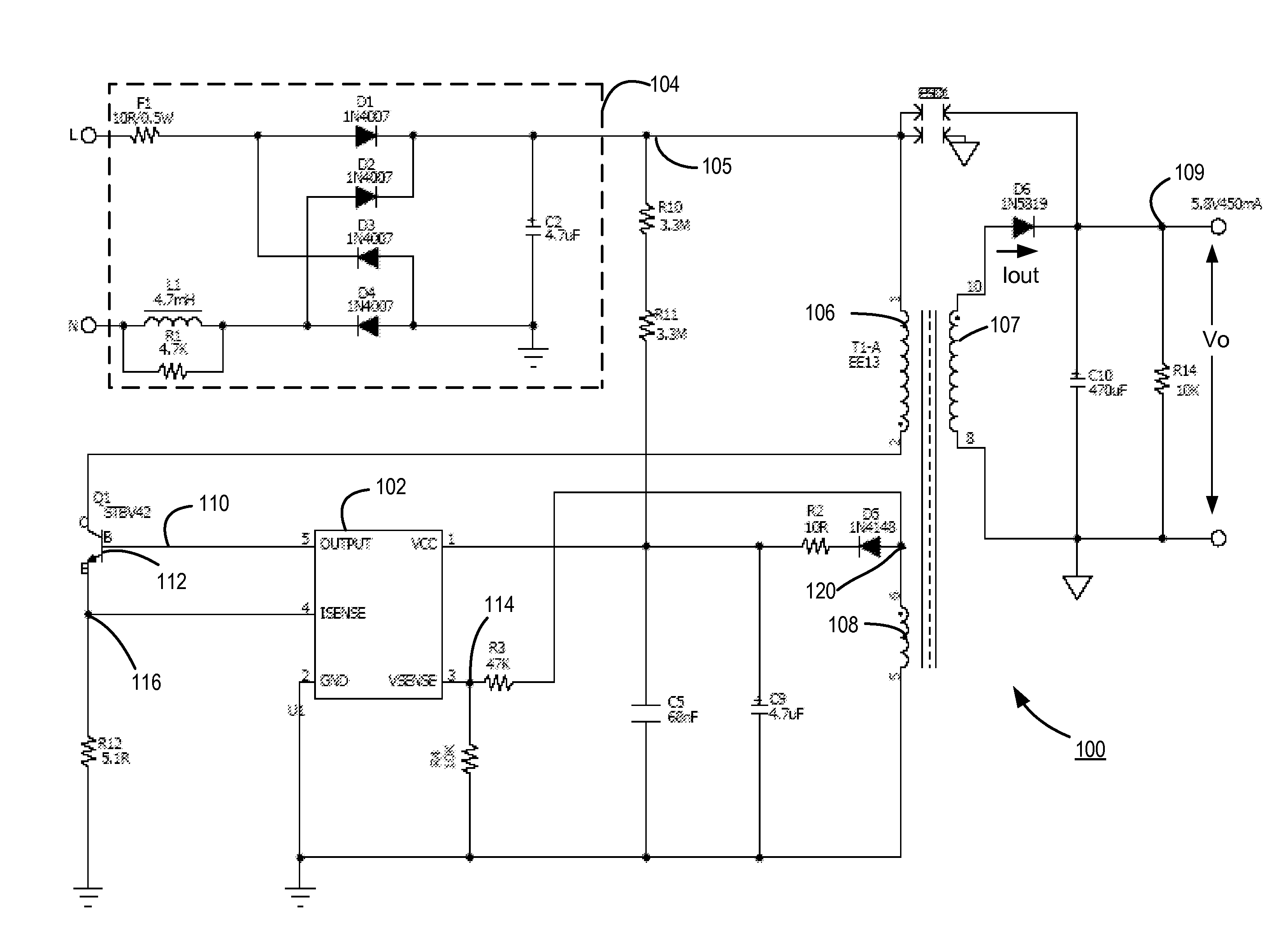
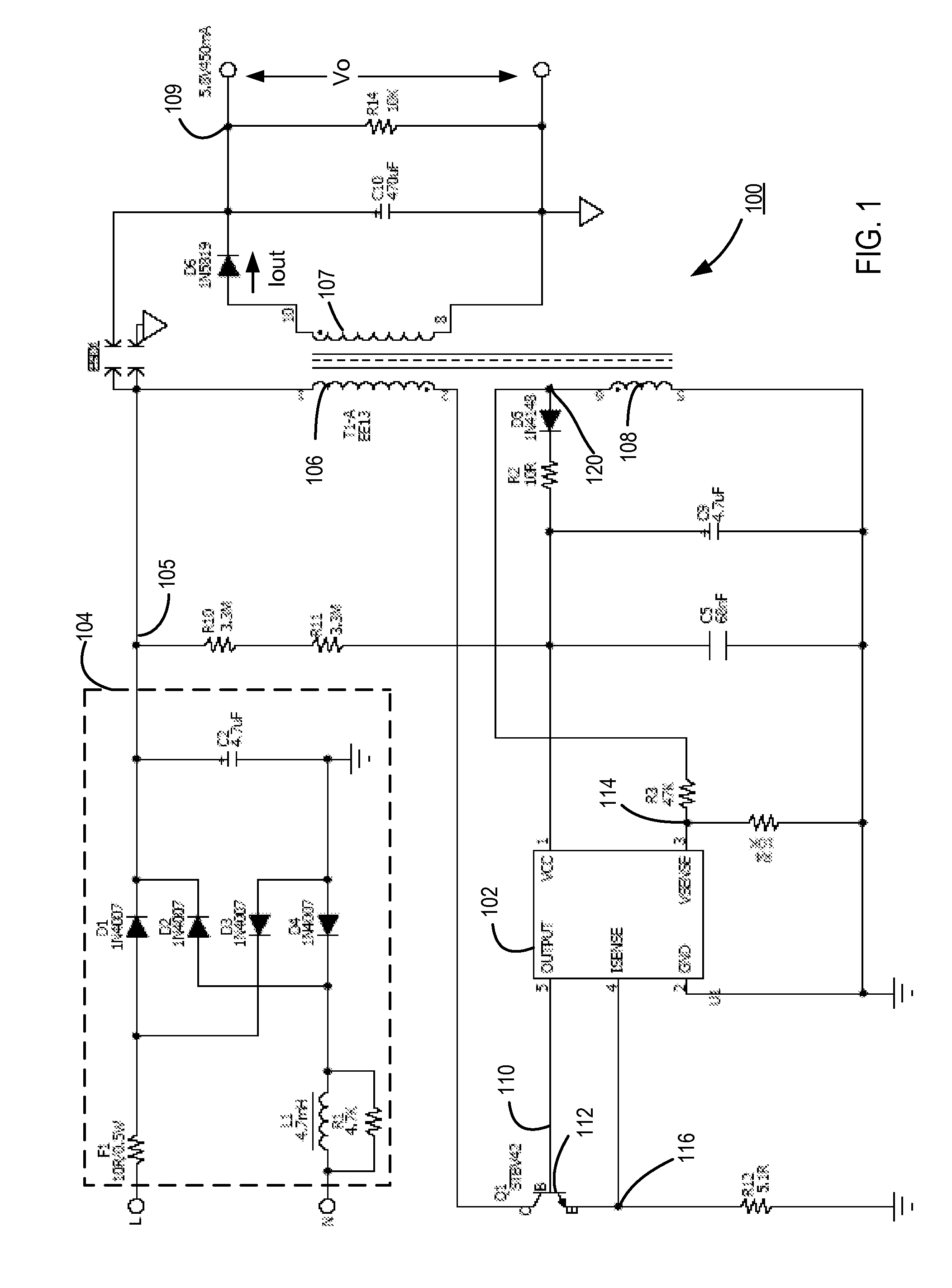
[0006]Embodiments include setting an actual turn-on time of a switch in a switching power converter in each switching cycle by selecting one of a plurality of valley points of the output voltage occurring subsequent to the desired turn-on time of the switch calculated according to the regulation scheme employed by the switching power converter, with the selection of one of the plurality of valley points done randomly from switching cycle to switching cycle. In one embodiment, the switching power converter may be turned on at either one of two valley points of the output voltage occurring subsequent to the desired turn-on time of the switch calculated according to the regulation scheme employed by the switching power converter, with the selection of one of two valley points occurring according to the value of a pseudo random number sequence. Turning on the switch at one of multiple valley points randomly selected results in spreading the frequency spectrum of EMI generated by the switching activities in the switching power converter, reducing the EMI energy in any one particular band. Furthermore, the VMS scheme according to the embodiments herein better isolates other devices coupled to the switching power converter from switching-induced EMI by limiting the variation of the instantaneous switching frequency.

Problems solved by technology

Each time a switch, such as a transistor, in a switching power converter is turned on or off, electromagnetic interference (EMI) related to the switching frequency is generated.
EMI generated by switching power converters, if not properly managed, can generate frequencies that actively interfere with the operation of other devices coupled to the switching power converters, or can otherwise encroach into frequency bands designated to be free from interfering frequencies.

Method used


Image

  • EMI Frequency Spreading Method for Switching Power Converter
  • EMI Frequency Spreading Method for Switching Power Converter
  • EMI Frequency Spreading Method for Switching Power Converter

Examples


Embodiment Construction

[0016]The Figures (FIG.) and the following description relate to preferred embodiments of the present disclosure by way of illustration only. It should be noted that from the following discussion, alternative embodiments of the structures and methods disclosed herein will be readily recognized as viable alternatives that may be employed without departing from the principles of the present disclosure.

[0017]Reference will now be made in detail to several embodiments of the present disclosure, examples of which are illustrated in the accompanying figures. It is noted that wherever practicable similar or like reference numbers may be used in the figures and may indicate similar or like functionality. The figures depict embodiments of the present disclosure for purposes of illustration only. One skilled in the art will readily recognize from the following description that alternative embodiments of the structures and methods illustrated herein may be employed without departing from the p...


PUM


Abstract

A controller of a switching power converter sets an actual turn-on time of a switch in the switching power converter in each switching cycle by selecting one of a plurality of valley points of the output voltage of the switching power converter occurring subsequent to the desired turn-on time of the switch. The desired turn-on time of the switch may be calculated according to the regulation scheme employed by the switching power converter. The controller selects one of the plurality of valley points randomly from switching cycle to switching cycle. The controller generates a control signal to turn on the switching power converter at the selected one of the plurality of valley points of the output voltage occurring subsequent to the desired turn-on time.

Description

CROSS REFERENCE TO RELATED APPLICATION[0001]This application claims priority under 35 U.S.C. §119(e) from co-pending U.S. Provisional Patent Application No. 61 / 560,766, filed on Nov. 16, 2011, which is incorporated by reference herein in its entirety.BACKGROUND[0002]1. Technical Field[0003]The present disclosure relates to improving electromagnetic interference frequency in a switching power converter operating in a valley-mode switching (VMS) scheme.[0004]2. Description of the Related Art[0005]Each time a switch, such as a transistor, in a switching power converter is turned on or off, electromagnetic interference (EMI) related to the switching frequency is generated. Large rates of change for voltages and / or currents (i.e., dv / dt and / or di / dt) at the time of the switch transition increase the amount of EMI produced by the switch. EMI generated by switching power converters, if not properly managed, can generate frequencies that actively interfere with the operation of other device...

Claims


Application Information

Patent Timeline
Patent Type & Authority Applications(United States)
IPC IPC(8): H02M7/217
CPCH02M1/44H02M3/33507H02M1/12H02M3/28
Inventor SHI, FUQIANGLI, YONGKESTERSON, JOHN WILLIAMNGUYEN, DAVIDZHENG, JUNJIE
Owner DIALOG SEMICONDUCTOR INC
Why Eureka
Try Eureka