Rotary pump with improved seal

Active Publication Date: 2013-05-16
SCHWABISCHE HUTTENWERKE AUTOMOTIVE CMBH
View PDF6 Cites 11 Cited by
  • Summary
  • Abstract
  • Description
  • Claims
  • Application Information

AI Technical Summary

Benefits of technology

[0005]It is an aim of the invention to more reliably ensure the setting of a requirement-adjusted de

Problems solved by technology

While the pump is in operation, however, fluid leaks from the high-pressure side of the delivery chamber into the control pressure chamber via the axial

Method used


Image

  • Rotary pump with improved seal
  • Rotary pump with improved seal
  • Rotary pump with improved seal

Examples


Embodiment Construction

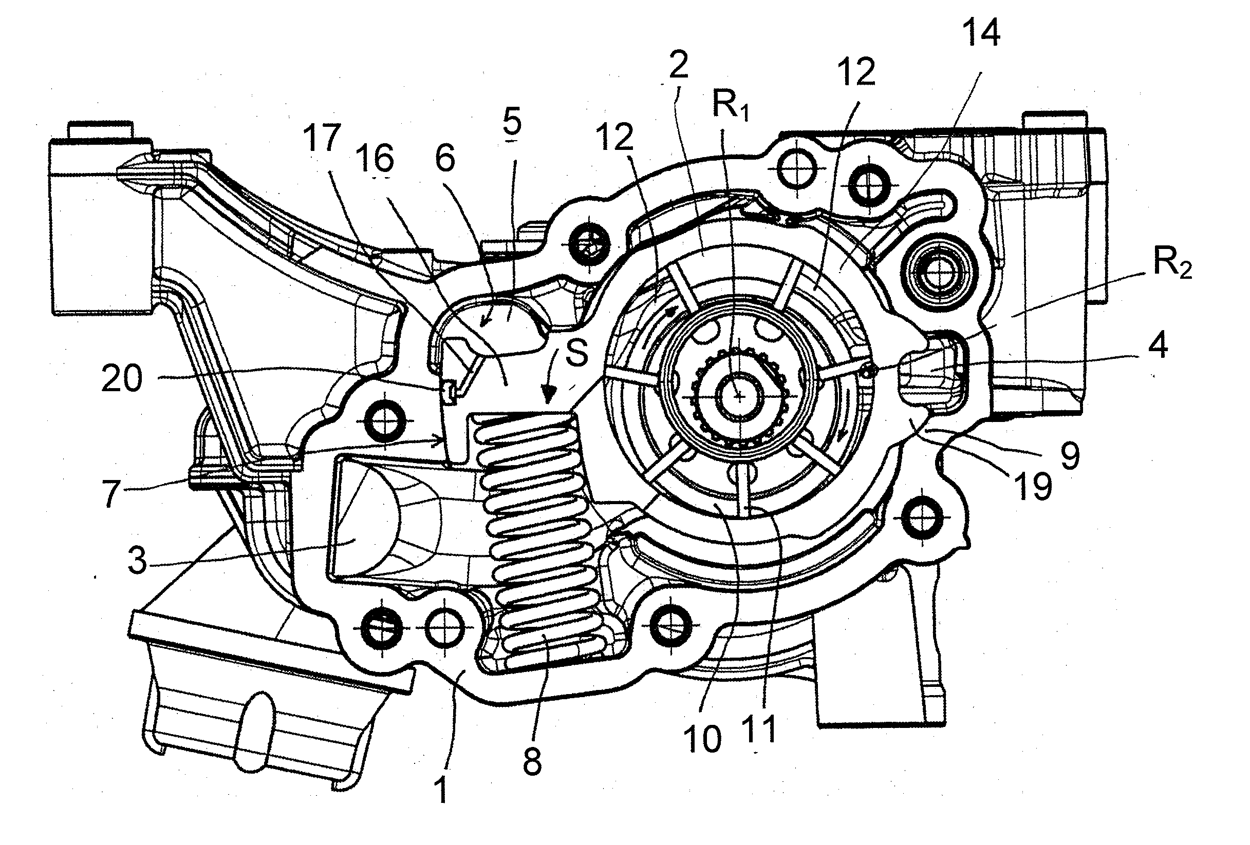
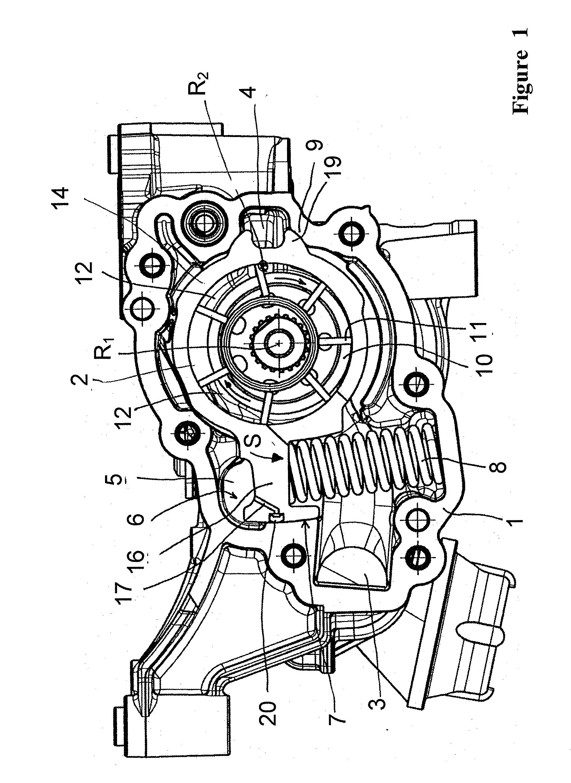
[0032]FIG. 1 shows a rotary pump, in a vane cell design by way of example. The pump is shown in a lateral view onto a pump housing 1 of the pump. A cover of the housing 1 has been removed, such that the functional components of the pump can be seen. The housing 1 forms a delivery chamber 2 in which a feed wheel 10 is arranged such that it can be rotated about a rotational axis R1. The housing 1 comprises an inlet featuring an inlet channel 3, and an outlet featuring an outlet channel 4, for the fluid. The delivery chamber 2 comprises a low-pressure side and a high-pressure side. When the feed wheel 10 is rotary-driven in the rotational direction indicated (clockwise), fluid flows via the inlet channel 3 on the low-pressure side into the delivery chamber 2 and is expelled on the high-pressure side at an increased pressure and withdrawn via the outlet channel 4.

[0033]The feed wheel 10 is a impeller comprising vanes 11 which are arranged in a distribution about the rotational axis R1. ...


PUM


Abstract

A rotary pump with an improved seal on a control pressure chamber, including: a housing having a delivery chamber; a feed wheel rotatable in the delivery chamber; an actuating member surrounding the feed wheel forming delivery cells and moveable in the housing relative to the feed wheel. The control pressure chamber is delineated by the actuating member together with axially facing axial co-operating surfaces, forming an axial sealing gap and a radial sealing gap. A control fluid can be introduced into the control pressure chamber for applying pressure to the actuating member to exert an actuating force in the actuating direction; a restoring device for generating a restoring force; and a sealing element arranged on the actuating member or the circumferential co-operating surface. To compensate for a change in gap width of one of the axial sealing gaps, a base leakage cross-section is provided on the sealing element.

Description

CROSS-REFERENCE TO RELATED APPLICATIONS[0001]This application claims priority to German Patent Application No. 10 2011 086 175.0, filed Nov. 11, 2011, the contents of such application being incorporated by reference herein.FIELD OF THE INVENTION[0002]The invention relates to a rotary pump, in particular a rotary displacement pump, with an improved seal in the region of a movable actuating member of the pump. The rotary displacement pump can in particular be a vane cell pump or reciprocating piston valve pump; however, other pumps can also in principle be realized using the invention.BACKGROUND OF THE INVENTION[0003]Rotary pumps comprise a rotatable feed wheel and, for adjusting their specific delivery volume, an actuating member which surrounds the feed wheel and can be moved back and forth and to which a control fluid is applied in one direction of its mobility and a restoring force is applied counter to the control fluid force exerted by the control fluid. The pressure of the cont...

Claims


Application Information

Patent Timeline
IPC IPC(8): F04C29/00
CPCF04C29/00F04C15/0034F04C14/226F04C2/344
Inventor EBINGER, JURGENEHRINGER, MICHAELFRIEDRICH, KIM BORISKUCHLE, STEFANMEMEL, BORISPETERS, SVENPREISLER, LOTHARSCHMID, ANTONWIGGENHAUSER, KLAUS
Owner SCHWABISCHE HUTTENWERKE AUTOMOTIVE CMBH
Why Eureka
Try Eureka