
Surface tracking and motion compensating surgical tool system

a surgical tool and surface tracking technology, applied in the field of surgical tools and systems, can solve the problems of physiological hand tremor, lack of tactile feedback in tool-to-tissue interaction, and inability to clearly view surgical targets

Inactive Publication Date: 2013-05-16
THE JOHN HOPKINS UNIV SCHOOL OF MEDICINE
View PDF2 Cites 31 Cited by
  • Summary
  • Abstract
  • Description
  • Claims
  • Application Information

AI Technical Summary

Benefits of technology

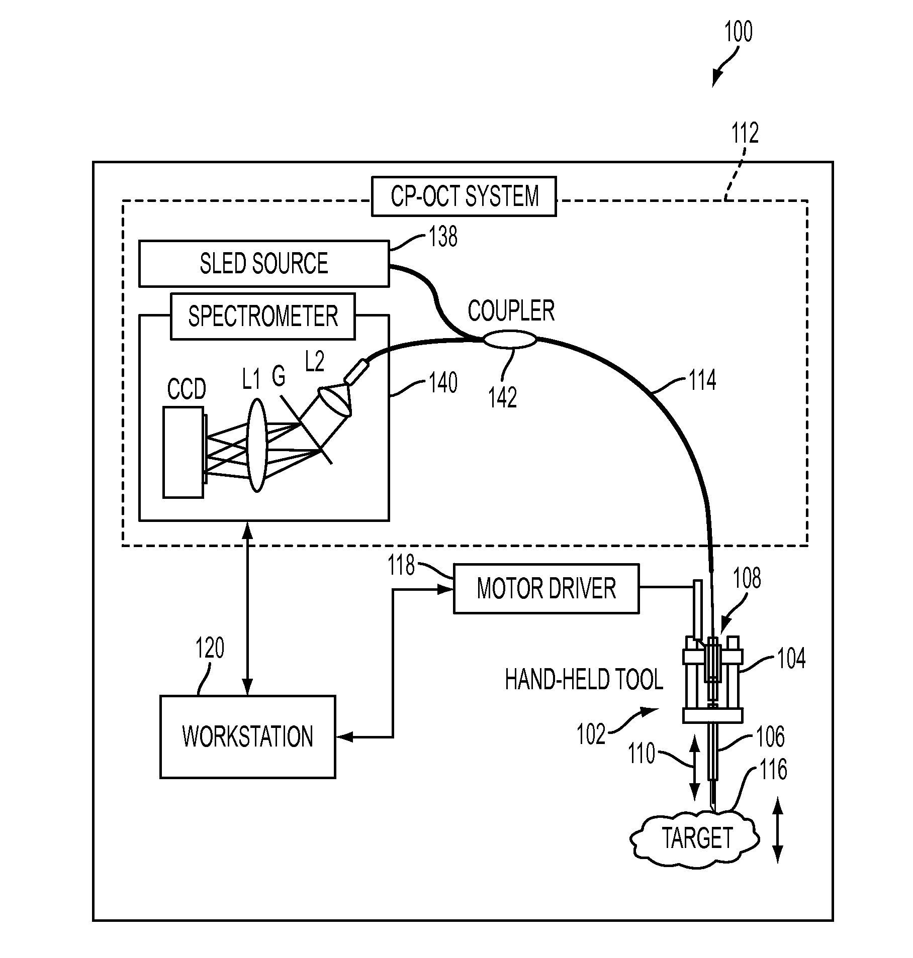
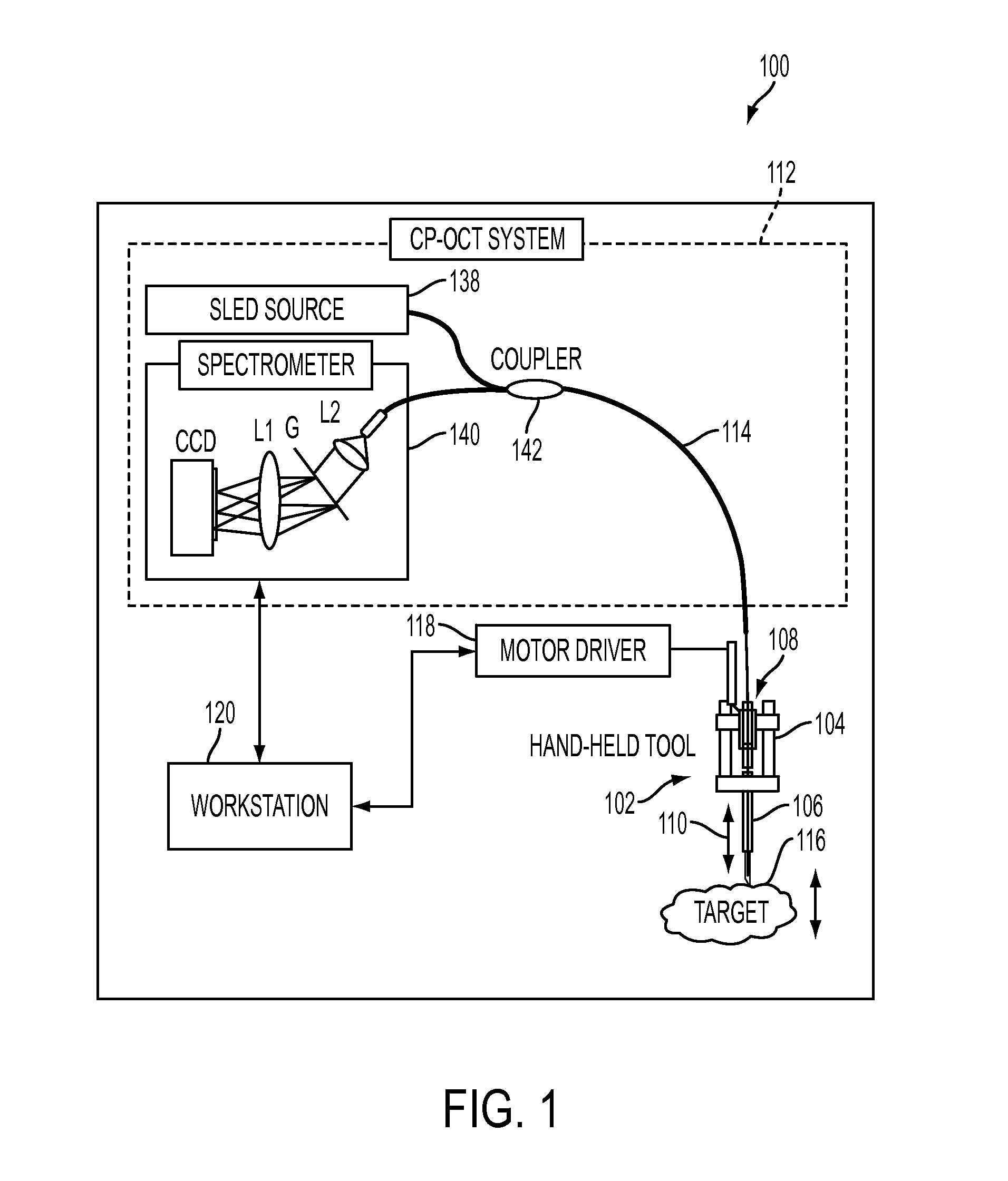
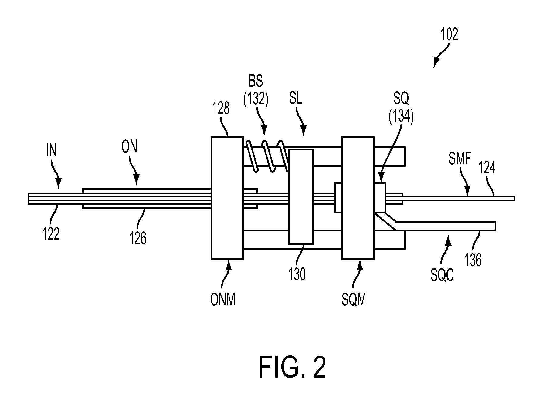
A motion-compensating surgical tool system includes a handpiece and a moveable component that can be moved in relation to the handpiece using a drive assembly. The system also includes an optical detection system that uses an optical fiber to determine the distance between the distal-most portion of the moveable component and a target during surgery. This allows for precise and accurate tool movement and positioning during surgery.

Problems solved by technology

Human limitations include an inability to clearly view surgical targets, physiological hand tremor, and lack of tactile feedback in tool-to-tissue interactions.
In addition, tool limitations, such as lack of proximity sensing or smart functions, are important factors that contribute to surgical risk and reduce the likelihood of achieving surgical goals.
Current instruments do not provide physiological or even basic interpretive information.
Surgical outcomes (both success and failure) are limited, in part, by technical hurdles that cannot be overcome by conventional instrumentation.
The resulting involuntary distance changes between the surgical tool and surgical tissue surface, although usually on the order of a few hundreds of micrometer at less than 5 Hz, may cause serious error due to the scale of microsurgery.

Method used


Image

  • Surface tracking and motion compensating surgical tool system
  • Surface tracking and motion compensating surgical tool system
  • Surface tracking and motion compensating surgical tool system

Examples


examples

[0039]First we implemented the surface tracking and motion compensation tests for an example. The surgical tool tip is pointed perpendicularly to a reflective target surface, which moves back and forth from the initial position. The tool tip senses the motion and adjusts to keep a constant distance D=1120 μm by moving together with the target surface. The error changing between d and D is recorded with time, and the compensation effect is apparent by comparing the error values between “Compensation off” mode and “Compensation on” mode, as in FIG. 6A. FIG. 6B shows a zoomed-in view of the error-time curve at “Compensation on” mode in FIG. 6A. The compensation error is within ±5 μm, which agrees well with the resolution of CP-OCT. The phase error can be further reduced by applying a predictive filter into the tracking algorithm (Zhang, K., Wang, W., Han, J-H., Kang, J. U., “A surface topology and motion compensation system for microsurgery guidance and intervention based on common-pat...


PUM


Abstract

A motion-compensating surgical tool system includes a surgical tool that includes a hand piece and a moveable component, a drive assembly connecting the moveable component to the hand piece such that the moveable component is movable in an axial direction relative to the hand piece by the drive assembly. The motion-compensating surgical tool system also includes an optical detection system that includes an optical fiber attached to the moveable component with an end at a fixed distance to a distal-most portion of the moveable component. The optical detection system is configured to output a signal for the determination of a distance of the distal-most portion of the moveable component to a target during surgery.

Description

CROSS-REFERENCE OF RELATED APPLICATION[0001]This application claims priority to U.S. Provisional Application No. 61 / 365,998 filed Jul. 20, 2010, the entire contents of which are hereby incorporated by reference.[0002]This invention was made with Government support of Grants No. 1R01 EB 007969-01 and 1R21NS063131-01A1, awarded by the Department of Health and Human Services, NIH. The U.S. Government has certain rights in this invention.BACKGROUND[0003]1. Field of Invention[0004]The field of the currently claimed embodiments of this invention relates to surgical tools and systems that incorporate the surgical tools, and more particularly to systems and surgical tools that have integrated surface tracking and motion compensation sensors.[0005]2. Discussion of Related Art[0006]Retinal surgery is one example of microsurgery. In current practice, retinal surgery is performed under an operating microscope with free-hand instrumentation. Human limitations include an inability to clearly view...

Claims


Application Information

Patent Timeline
Patent Type & Authority Applications(United States)
IPC IPC(8): A61B17/00
CPCA61B3/102A61B3/113A61B19/22A61B2017/00225A61B2017/00402A61B2017/00694A61B17/00A61B2019/2249A61B2019/2288A61F9/00727A61B2017/00057A61B2017/00061A61B2017/00075A61B2017/305A61B34/70A61B34/72A61B34/75A61B3/10A61F9/007
Inventor KANG, JIN UNGGEHLBACH, PETERTAYLOR, RUSSELL H.ZHANG, KANG
Owner THE JOHN HOPKINS UNIV SCHOOL OF MEDICINE
Learn More