Facet interference cage

a facet and cage technology, applied in the field of facet interference cages, can solve the problems of time-consuming and invasive procedures

Active Publication Date: 2013-05-16
DEPUY SYNTHES PROD INC
View PDF14 Cites 96 Cited by
  • Summary
  • Abstract
  • Description
  • Claims
  • Application Information

AI Technical Summary

Problems solved by technology

These implants and / or fixation devices may be bulky, causing patient-discomfort and requiring time-consuming, invasive procedures.

Method used


Image

  • Facet interference cage
  • Facet interference cage
  • Facet interference cage

Examples


Embodiment Construction

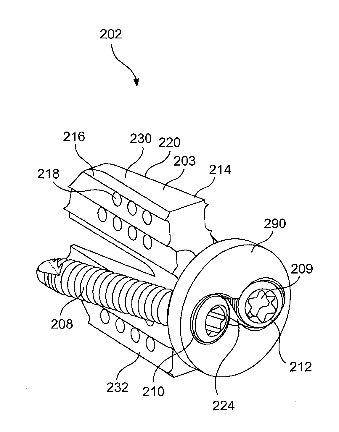
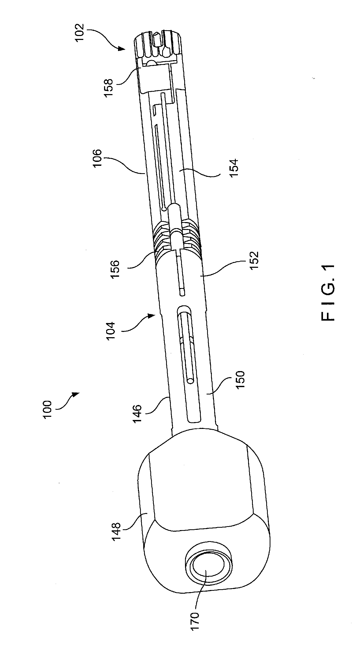
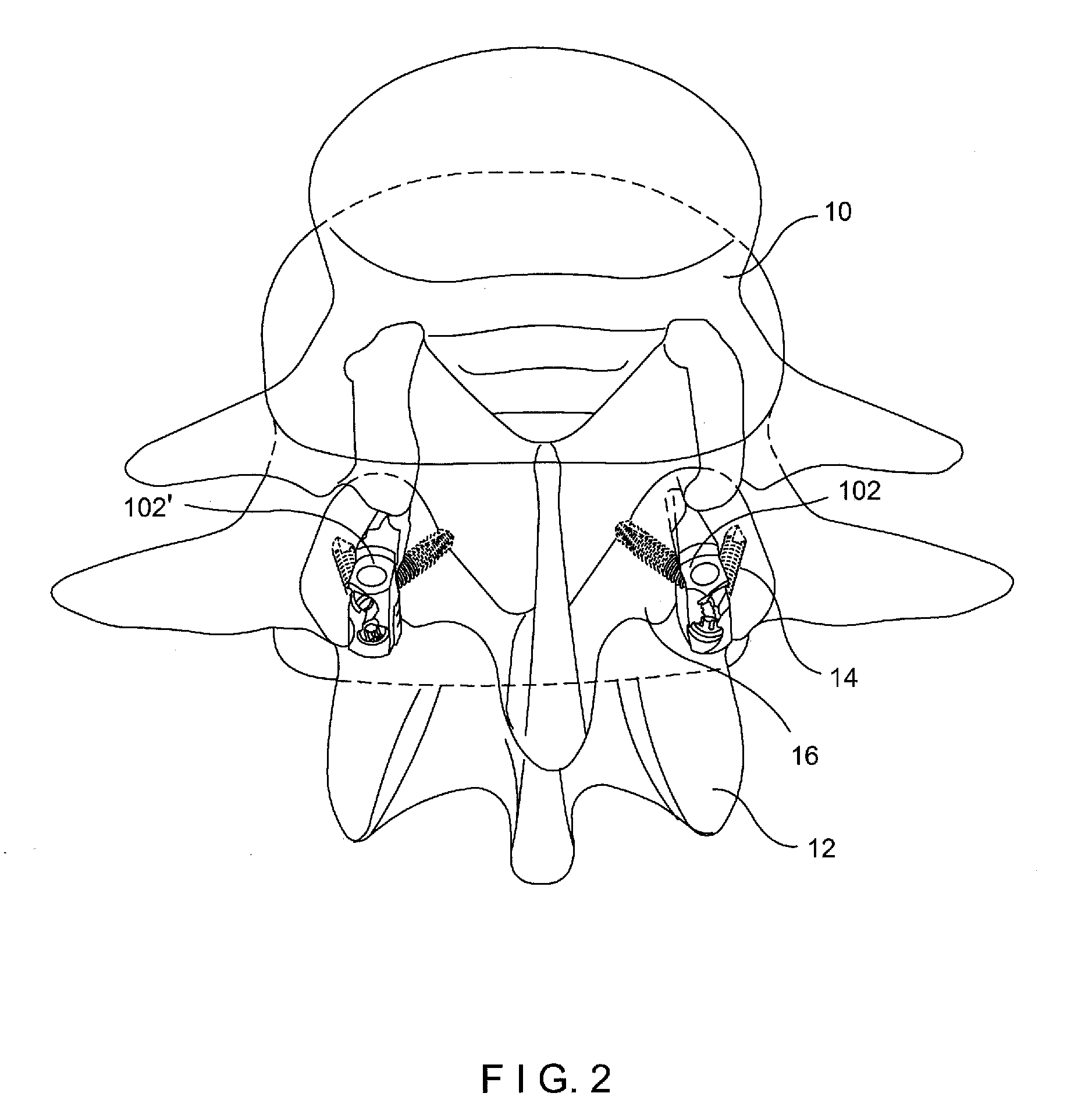
[0075]The present invention may be further understood with reference to the following description and the appended drawings, wherein like elements are referred to with the same reference numerals. The present invention relates to bone treatment devices and, in particular, relates to a minimally invasive posterior fusion device. Exemplary embodiments of the present invention describe a system and method for posterior spinal fusion, including an implant shaped for insertion into a facet joint of adjacent vertebra along with an insertion tool to facilitate proper insertion and fixation thereof. It will be understood by those of skill in the art that the system and method of the present invention utilize a faster, less invasive technique which requires less muscle stripping and does not require the usage of pedicle screws for stabilization. It should be noted that the terms “proximal” and “distal” as used herein, are intended to refer to a direction toward (proximal) and away from (dist...


PUM


Abstract

An implant includes a body sized and shaped for insertion into a facet joint, the implant including a first bone fixation element receiving opening extending through a portion thereof along a first axis oriented so that, when the implant is received within a facet joint in a desired configuration, a bone fixation element inserted into the first bone fixation element receiving opening will extend into a first one of the vertebra forming the facet joint.

Description

PRIORITY CLAIM[0001]The present application claims priority to U.S. Provisional Application Ser. No. 61 / 484,441 entitled “Implant and Tool” filed on May 10, 2011, U.S. Provisional Application Ser. No. 61 / 527,878 entitled “Facet Interference Cage” filed on Aug. 26, 2011 and U.S. Provisional Application Ser. No. 61 / 602,927 entitled “Facet Interference Cage” filed on Feb. 24, 2012, the entire disclosure of which are incorporated herein by reference.BACKGROUND[0002]Posterior spinal fusion may be achieved using, for example, screws, rods and / or plates to fix two or more adjacent vertebrae relative to one another and facilitate fusion. Pedicle screws are used to add extra support to prevent the vertebrae from moving while fusing. These implants and / or fixation devices may be bulky, causing patient-discomfort and requiring time-consuming, invasive procedures.SUMMARY OF THE INVENTION[0003]The present invention is directed to an implant comprising a body sized and shaped for insertion into a...

Claims


Application Information

Patent Timeline
Patent Type & Authority Applications(United States)
IPC IPC(8): A61B17/70A61F2/44
CPCA61F2/4455A61F2002/4687A61B17/0206A61B17/1671A61B17/7064A61B2019/304A61F2/30767A61F2002/30029A61F2002/30306A61F2002/30471A61F2002/30576A61F2002/30578A61F2002/30785A61F2002/30787A61F2002/30828A61F2002/30879A61F2002/30904A61F2002/3093A61F2/4405A61F2/4611A61B17/1697A61B17/70A61F2/442A61F2002/30542A61B2090/034A61F2002/30028A61F2002/3054
Inventor PAVLOV, PAULOVERES, TOMFRIGG, ROBERTLINDENMANN, PHILIPPE
Owner DEPUY SYNTHES PROD INC
Why Eureka
Try Eureka