Electrical limitation of a steering gear travel path

a technology of steering gear and travel path, which is applied in the direction of steering initiation, instruments, vessel construction, etc., can solve the problems of limiting the possible steering angle and limited steering angl

Inactive Publication Date: 2013-05-16
GM GLOBAL TECH OPERATIONS LLC
View PDF18 Cites 8 Cited by
  • Summary
  • Abstract
  • Description
  • Claims
  • Application Information

AI Technical Summary

Benefits of technology

[0008]Because the steering drive itself is used to acquire a maximum travel path, the latter can be acquired very easily and precisely. This advantageously makes it easier to repeat the acquisition and presetting, in one example, in an automated way, when one or more components of the steering gear whose formation and / or assembly influences the maximum travel path of the steering gear have been changed out in the tolerance chain of the steering gear. In like manner, the acquisition and presetting can be performed quickly and precisely during an initial assembly of the vehicle.
[0011]Once a maximum travel path has been reached, for example given physical contact between the steered wheel and wheel case, steering link and wheel rim or the like, a force in the steering gear rises to counter any further travel motion. The acquisition means of the steering gear can acquire this rise in force and the travel path where it is encountered, and thereby acquire the maximum travel path in a simple and precise manner.
[0021]In another exemplary embodiment, the steering drive adjusts the steering gear in the first and / or second direction, so as to acquire a maximum travel path. This advantageously enables an automated acquisition and presetting, and hence an automated setting, of the electrical travel path limitation of the steering gear, in one example, when changing out a component in the tolerance chain.

Problems solved by technology

The free space for a wheel in a wheel case limits the possible steering angle.
Therefore, the steering angle is limited, generally to prevent the steered wheel from touching the wheel case.

Method used


Image

  • Electrical limitation of a steering gear travel path
  • Electrical limitation of a steering gear travel path

Examples


Embodiment Construction

[0030]The following detailed description is merely exemplary in nature and is not intended to limit the present disclosure or the application and uses of the present disclosure. Furthermore, there is no intention to be bound by any theory presented in the preceding background or the following detailed description.

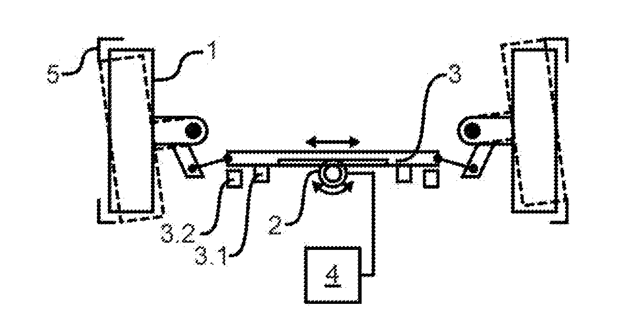
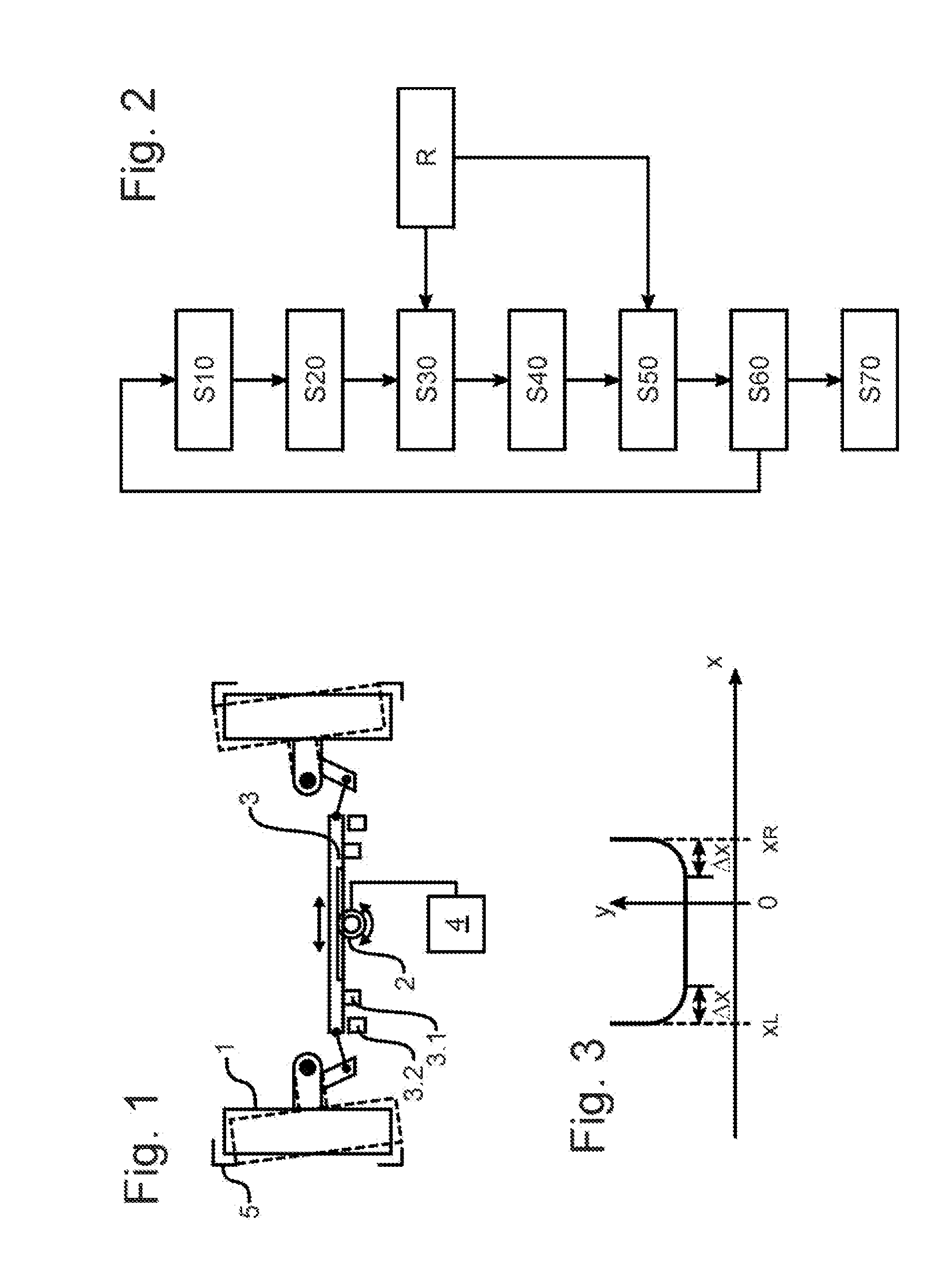
[0031]FIG. 1 presents an exemplary view of a steering gear for a passenger car according to an exemplary embodiment of the present disclosure with two wheels 1 that are steered by means of a steering rack 3 and housed in wheel cases 5. In order to shift the steering rack 3, an electromotor 2 of a steering drive engages the latter, which supports a steering motion of a steering rod (not shown) operatively connected with a steering wheel, or moves the steering rack decoupled from the steering wheel by itself based upon an acquired steering activation of the steering wheel.

[0032]In addition to the electromotor 2, the steering drive in one example, encompasses a controller 4 co...


PUM


Abstract

A method for an electrical limitation of the travel path of a steering gear in a wheeled vehicle, in particular a passenger car, which exhibits a steering drive, is provided. The method includes adjusting the steering gear in a first direction and acquiring a first maximum travel path in the first direction. The method includes prescribing a first limiting value based upon this acquired first maximum travel path and electrically limiting the travel path of the steering gear in the first direction based upon the first limiting value. The first maximum travel path is acquired by the steering drive.

Description

CROSS-REFERENCE TO RELATED APPLICATION[0001]This application claims priority to German Patent Application No. 10 2011 122 772.9, filed Nov. 2, 2011, which is incorporated herein by reference in its entirety.TECHNICAL FIELD[0002]The present disclosure relates to a method for electrically limiting the travel path of a steering gear in a wheeled vehicle, in particular a passenger car, as well as a to a steering gear set up for implementing such a method.BACKGROUND[0003]The free space for a wheel in a wheel case limits the possible steering angle. Therefore, the steering angle is limited, generally to prevent the steered wheel from touching the wheel case.[0004]In order to prescribe a permissible steering angle for several identically constructed vehicles under varying dynamic conditions, attention must be paid to dynamic changes on the one hand, for example compression, and also to component and assembly tolerances between the different vehicles on the other, for example a variable ass...

Claims


Application Information

Patent Timeline
Patent Type & Authority Applications(United States)
IPC IPC(8): B62D15/02
CPCB62D15/02B62D5/0469B62D3/12
Inventor DEGENSTEIN, THOMAS
Owner GM GLOBAL TECH OPERATIONS LLC
Why Eureka
Try Eureka