Wave power plant

a power plant and wave technology, applied in the direction of machines/engines, vessels, transportation and packaging, etc., can solve the problems of reducing the efficiency of the rotator, so as to improve the preconditions for varying wave conditions.

Inactive Publication Date: 2013-05-23
WELLO
View PDF6 Cites 2 Cited by
  • Summary
  • Abstract
  • Description
  • Claims
  • Application Information

AI Technical Summary

Benefits of technology

[0004]The aim of the present invention is to provide an improved wave power plant by means of which the output of the wave power plant can be increased and its operational preconditions in varying wave conditions can be improved.

Problems solved by technology

The problem with these known wave power plants is that the torque enhancing the rotation of the rotator shaft is received on it only for a short time, twice during a full rotation of the rotator, whereas at the intermediate stages, when the gyro shaft turns, the moment of the momentum of the rotation of the gyro generates a torque which inclines the body.
If the body is able to incline in the direction of the torque, it will perform unnecessary work and brake the rotation of the rotator.
It is thus difficult to make the rotator rotate in step with the waves.

Method used


Image

  • Wave power plant
  • Wave power plant
  • Wave power plant

Examples


Embodiment Construction

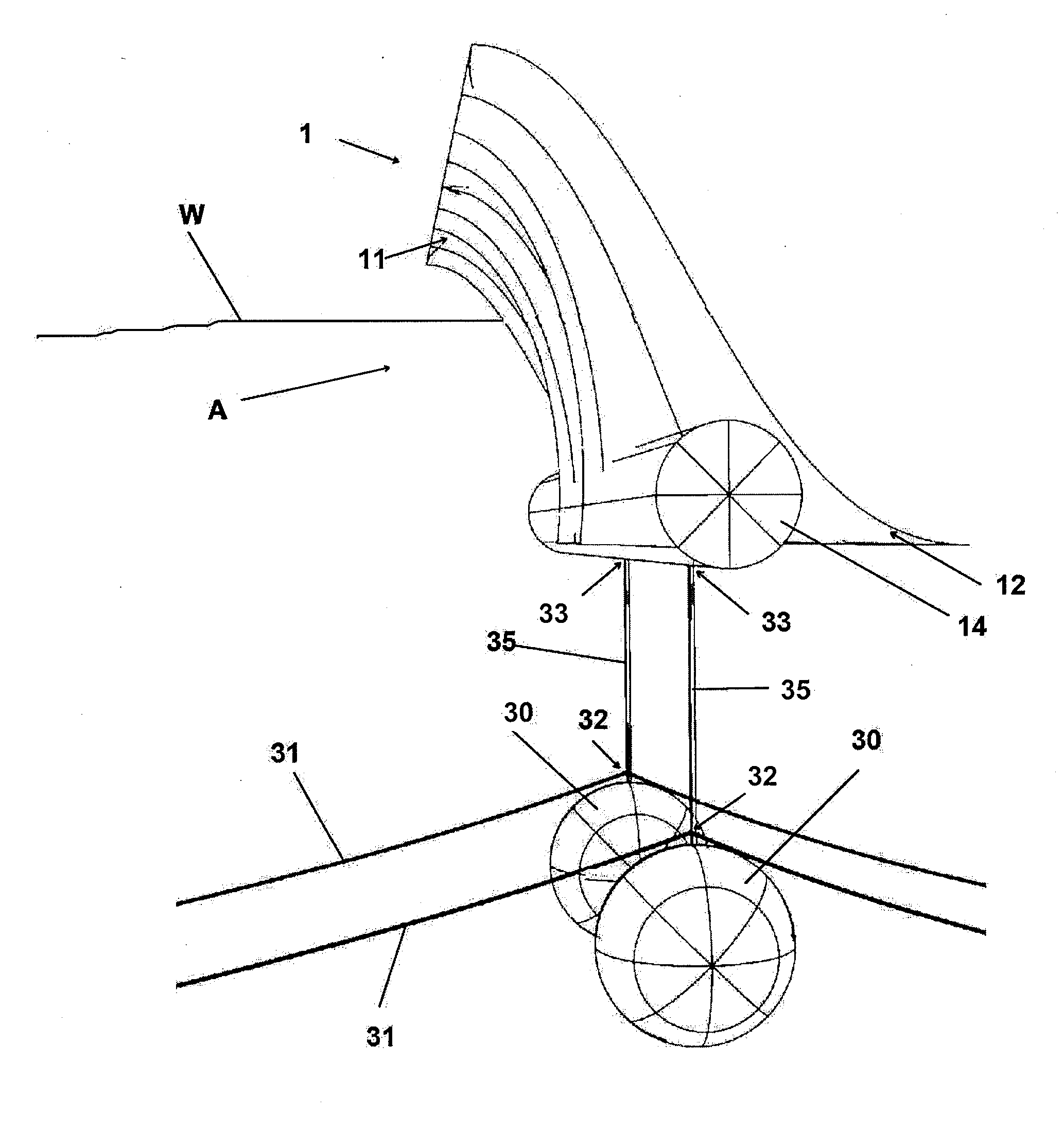
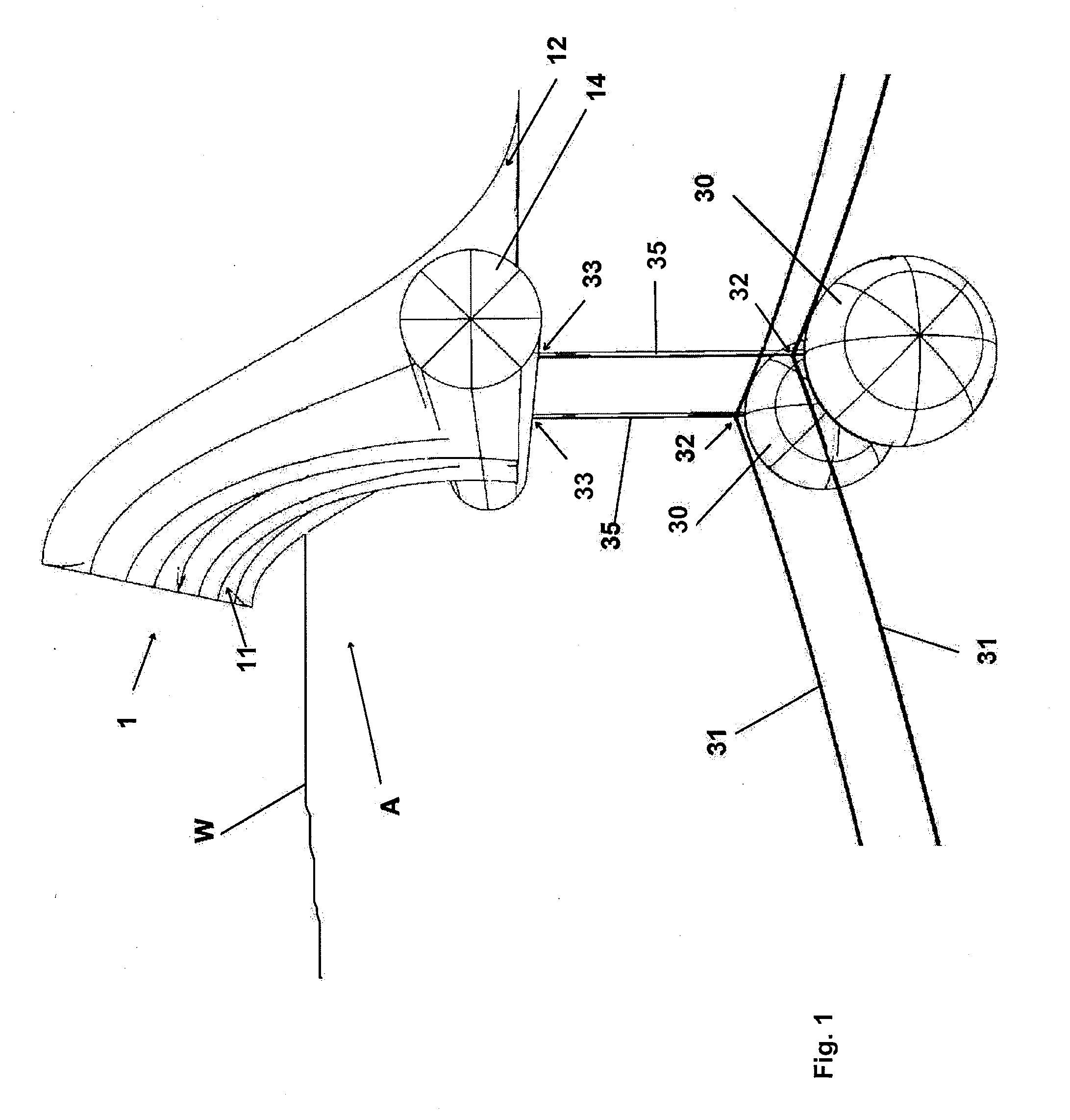
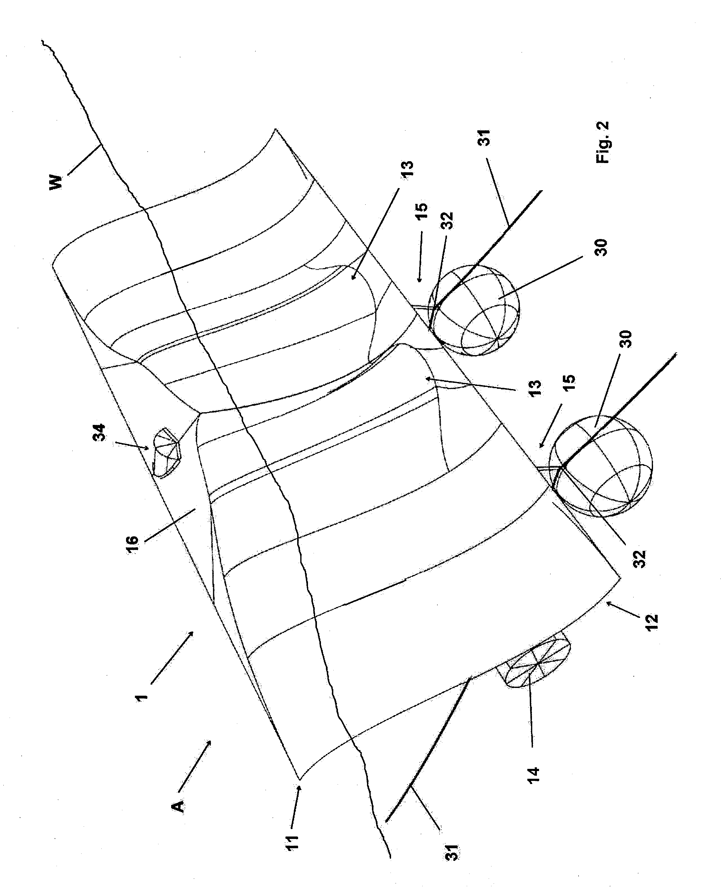
[0012]FIGS. 1 to 2 show a diagrammatic view in principle of a preferred embodiment of the body 1 of the wave power plant. The body 1 is a wall which is mainly vertical, or when in operation, inclined on average in the incoming direction of the wave, and which is for the most part below the water level W, but with its upper part above the water level. The wall-type shape and mainly vertical or inclined position converts the flow energy of the waves into kinetic energy efficiently and over a large surface area. The draught of the body 1 is preferably dimensioned to correspond to 0.5 H the length of the smallest functional wave desired, thus equaling the movement of the said wave in the vertical direction. In the exemplary implementation according to the Figures, the upper part 11 of the front side of the body 1 opposite to the main incoming direction A of the waves is designed to curve forward and the lower part 12 to curve backwards, thus forming a gently sloping letter S in cross-se...


PUM


Abstract

The invention relates to a wave power plant, comprising a floating body and means for converting the wave energy received by the body into electric power. The wave power plant comprises anchoring means arranged in the lower part of the body, the means including an anchoring mass suspended on a downwards extending elongated anchoring device. In connection with the anchoring mass are arranged transversely extending elongated anchoring devices which are connected to the bottom of the installation site of the wave power plant.

Description

BACKGROUND OF THE INVENTION[0001]1. Field of the Invention[0002]The present invention relates to a wave power plant, comprising a floating body and means for converting the wave energy received by the body into electric power.[0003]2. Description of the Related ArtSUMMARY OF THE INVENTION[0004]The aim of the present invention is to provide an improved wave power plant by means of which the output of the wave power plant can be increased and its operational preconditions in varying wave conditions can be improved.[0005]To achieve this aim, the wave power plant according to the present invention is characterised in that the body is a mainly vertical wall, which is for the most part below the water level W, but with its upper part above the water level, and that the wave power plant comprises anchoring means arranged in the lower part of the body, the means including an anchoring mass suspended in an articulated manner on a downwards extending elongated anchoring device connected to th...

Claims


Application Information

Patent Timeline
Patent Type & Authority Applications(United States)
IPC IPC(8): F03B13/16
CPCF03B13/16Y02E10/38F03B13/20F03B13/1825F05B2240/917F05B2240/93B63B2035/4466Y02E10/30B63B21/50
Inventor PAAKKINEN, HEIKKI
Owner WELLO
Why Eureka
Try Eureka