Image display device and light source cooling method
Active Publication Date: 2013-05-23
SHARP NEC DISPLAY SOLUTIONS LTD
View PDF6 Cites 10 Cited by
Summary
Abstract
Description
Claims
Application Information
AI Technical Summary
This helps you quickly interpret patents by identifying the three key elements:
Problems solved by technology
Method used
Benefits of technology
[0017]An object of the present invention is to provide an image display device and a light source cooling method that prevents the occurrence of photo-darkening phenomenon in the energy saving mode an
Problems solved by technology
However, the projection type display device described in Patent Literature 1 has the following problems.
Thus, if the projection type display device has been operated in the energy saving mode over a some considerable time, photo-darkening will occur
Method used
Image
Click on the blue label to locate the original text in one second.
Reading with bidirectional positioning of images and text.
Examples
first embodiment
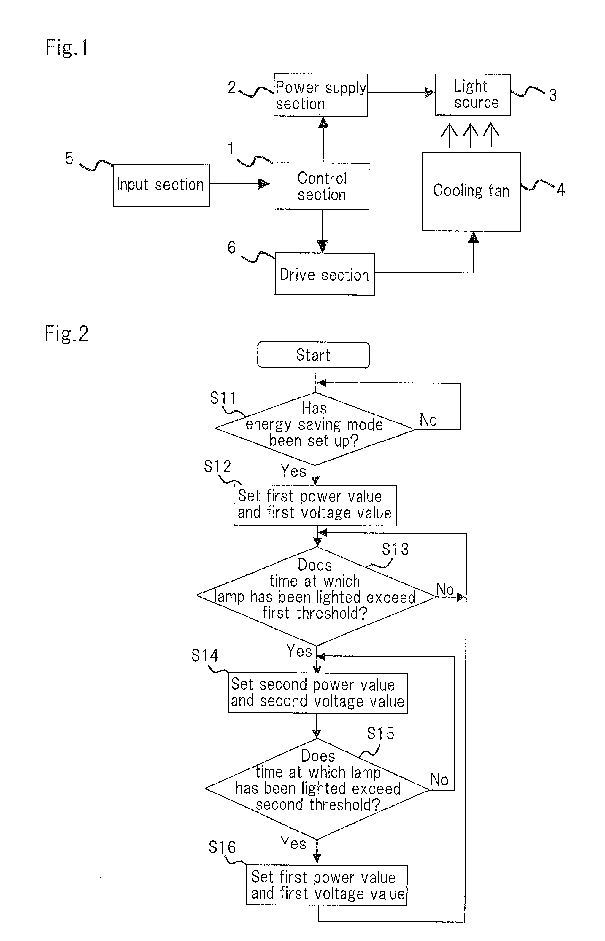
[0044]FIG. 1 is a block diagram showing the structure of an image display device according to a first embodiment of the present invention.
[0045]The image display device shown in FIG. 1 is an image display device that has a high pressure mercury lamp or the like as light source 3 and that displays an image in which light emitted from light source 3 has been spatially modulated. The image display device has control section 1, power supply section 2, light source 3, cooling fan 4, input section 5, and drive section 6.
[0046]Power supply section 2 supplies power to light source 3. Cooling fan 4 cools light source 3. Drive section 6 supplies a voltage to cooling fan 4.
[0047]Input section 5 has a plurality of buttons. The user can designate any one of a plurality of lighting modes using at least one of these buttons. The plurality of lighting modes include a regular mode in which the output of power supply section 2 is the maximum power value and an energy saving mode in which the output o...
second embodiment
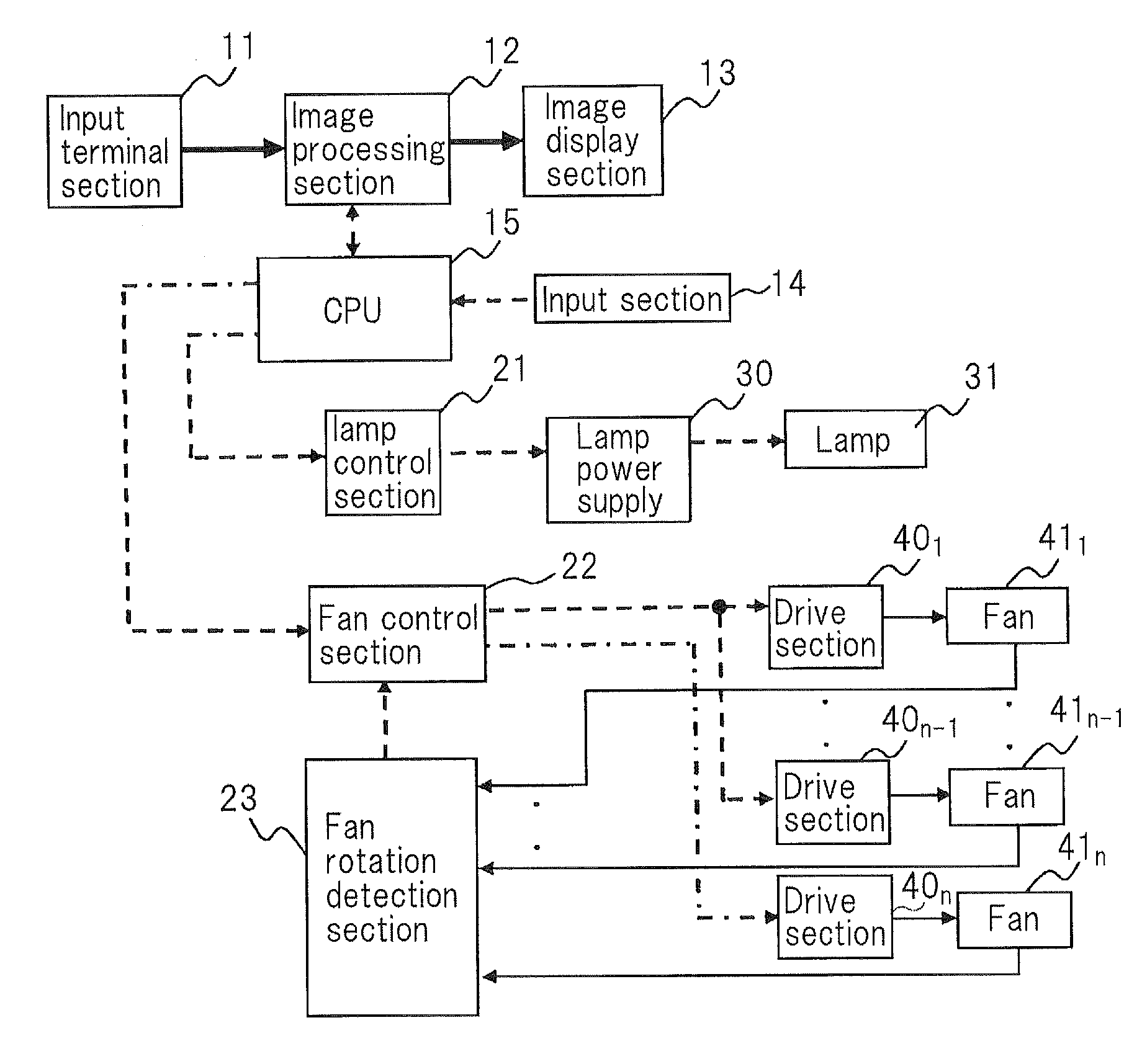
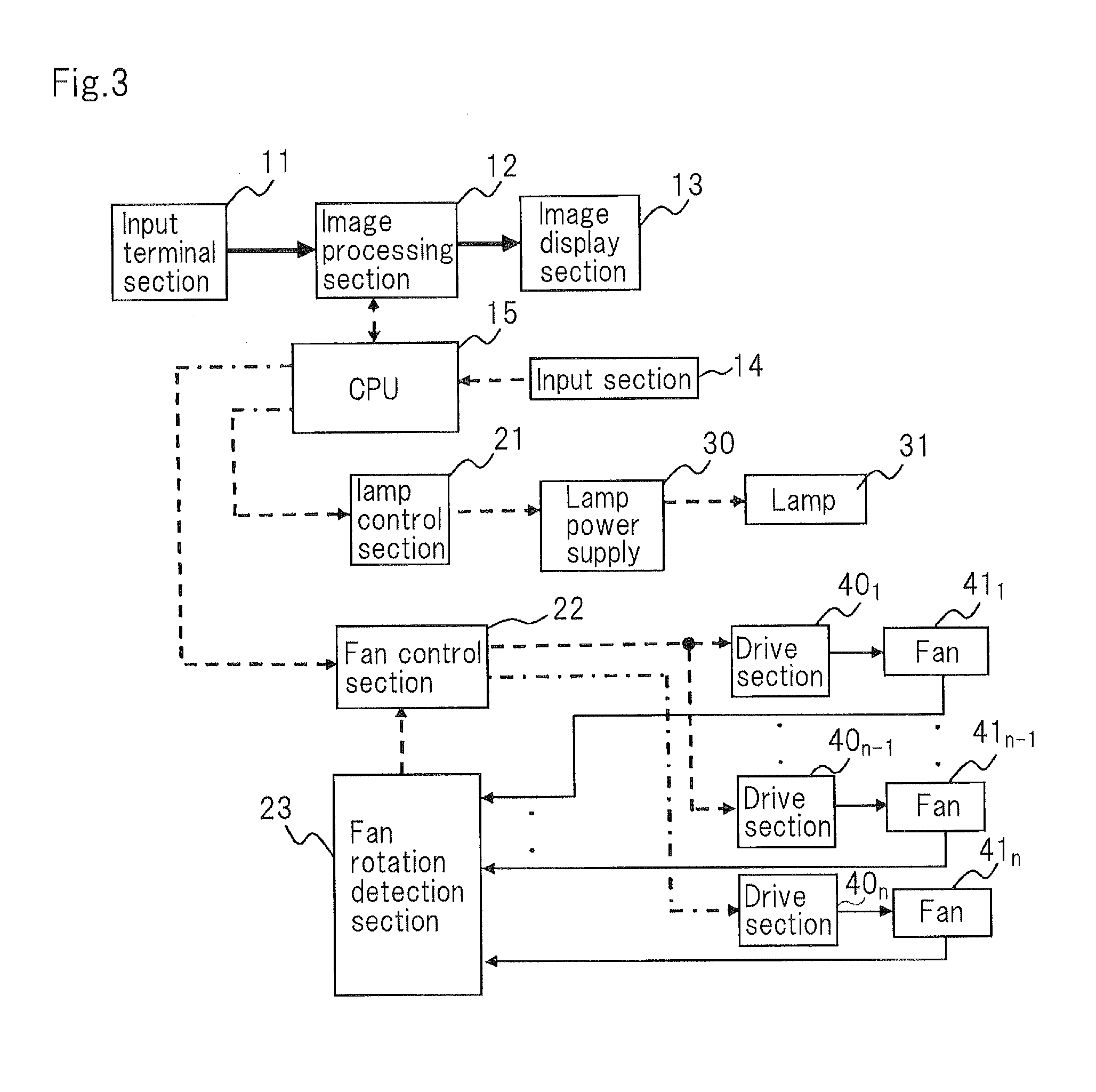
[0066]FIG. 3 is a block diagram showing the structure of an image display device according to a second embodiment of the present invention.
[0067]Referring to FIG. 3, the image display device has input terminal section 11, image processing section 12, image display section 13, input section 14, CPU (Central Processing Unit) 15, lamp control section 21, fan control section 22, fan rotation detection section 23, lamp power supply 30, lamp 31, drive sections 401 to 40n, and fans 411 to 41n.
[0068]Lamp 31 is a high pressure mercury lamp or the like. Lamp power supply 30 supplies power to lamp 31. Lamp control section 21 controls lamp power supply 30 to supply power to lamp 31 corresponding to a lamp control signal that is received from CPU 15. Specifically, lamp control section 21 outputs an ON / OFF signal that is a power supply control signal and a power designation signal that represents a power value.
[0069]An image signal is supplied from an external image supply unit to image processin...
PUM
Abstract
An image display device includes a light source; a power supply section that supplies power to light source; a cooling fan that cools the light source; an input section; a drive section that supplies a voltage to cooling fan; a control section that controls drive section and power supply section. The control section sets a first power value for the output of the power supply section and also a first voltage value for the output of the drive section. The control section measures a time at which the light source has been lighted. If the measured value exceeds a threshold, the control section gradually increases the output of the power supply section up to a second power value that is greater than the first voltage value over a predetermined time.
Description
TECHNICAL FIELD[0001]The present invention relates to an image display device provided with a light source such as a high pressure mercury lamp.BACKGROUND ART[0002]An image display device such as a liquid crystal display or a projector is provided with a high pressure mercury lamp or the like as a light source. A high pressure mercury lamp is structured such that mercury or gas is confined in a glass tube. Thus, if the temperature of the lamp excessively rises, the glass tube will explode or quartz that composes the glass tube will deform and thereby its permeability will deteriorate. To prevent such situations, image display devices that use a high pressure mercury lamp as a light source are generally provided with a cooling fan that cools the light source.[0003]Some of recent projectors that have a high pressure mercury lamp as a light source are provided with an energy saving mode that allows power supplied to the light source to be decreased to around several ten % of the maximu...
Claims
Application Information
Patent Timeline
Application Date:The date an application was filed.
Publication Date:The date a patent or application was officially published.
First Publication Date:The earliest publication date of a patent with the same application number.
Issue Date:Publication date of the patent grant document.
PCT Entry Date:The Entry date of PCT National Phase.
Estimated Expiry Date:The statutory expiry date of a patent right according to the Patent Law, and it is the longest term of protection that the patent right can achieve without the termination of the patent right due to other reasons(Term extension factor has been taken into account ).
Invalid Date:Actual expiry date is based on effective date or publication date of legal transaction data of invalid patent.