Systems and Methods for Separating Sand from Oil

a technology of separating system and oil, which is applied in the direction of filtration separation, separation process, and wellbore/well accessories, etc., can solve the problems of increasing the cost of apparatus, difficult transportation and installation, and mixing of oil with other substances, so as to reduce the erosion of the separation chamber wall and increase the taper angle

Inactive Publication Date: 2013-05-30
TAPER LOK
View PDF0 Cites 15 Cited by
  • Summary
  • Abstract
  • Description
  • Claims
  • Application Information

AI Technical Summary

Benefits of technology

[0012]The apparatus may include an abrasion-resistant liner positioned within the separation chamber to reduce erosion of the separation chamber wall. The separation chamber may be tapered so that the upper inner diameter of the separation chamber is larger than the lower inner diameter of the separation chamber. In one embodiment, the taper is between 5 and 10 degrees, but alternative embodiments may have greater taper angles. The apparatus may include a vortex plate positioned near the lower end of the separation chamber to prevent vortices in the separation chamber from extending into the accumulation chamber.

Problems solved by technology

Often, in the production of oil from wells, the oil is mixed with other, unwanted substances.
There are various problems with the use of conventional sand separators to remove sand from oil or other fluids.
The large size of the apparatus can make it difficult to transport and install.
Additionally, because of material cost, the sheer size of apparatus makes it more expensive.
Another problem is that it is difficult to accommodate the different operating conditions and fluid characteristics that may exist in different wells.
For instance, one well may have a higher flow rate than another, so the settling of the sand out of the faster-flowing fluid may be less effective.

Method used


Image

  • Systems and Methods for Separating Sand from Oil
  • Systems and Methods for Separating Sand from Oil
  • Systems and Methods for Separating Sand from Oil

Examples


Embodiment Construction

[0024]One or more embodiments of the invention are described below. It should be noted that these and any other embodiments described below are exemplary and are intended to be illustrative of the invention rather than limiting.

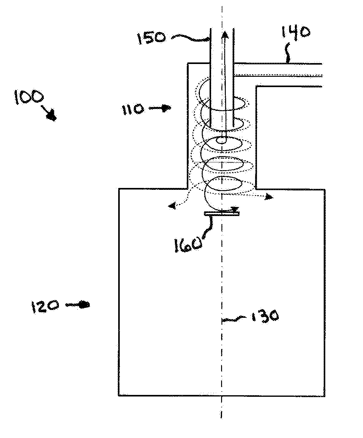
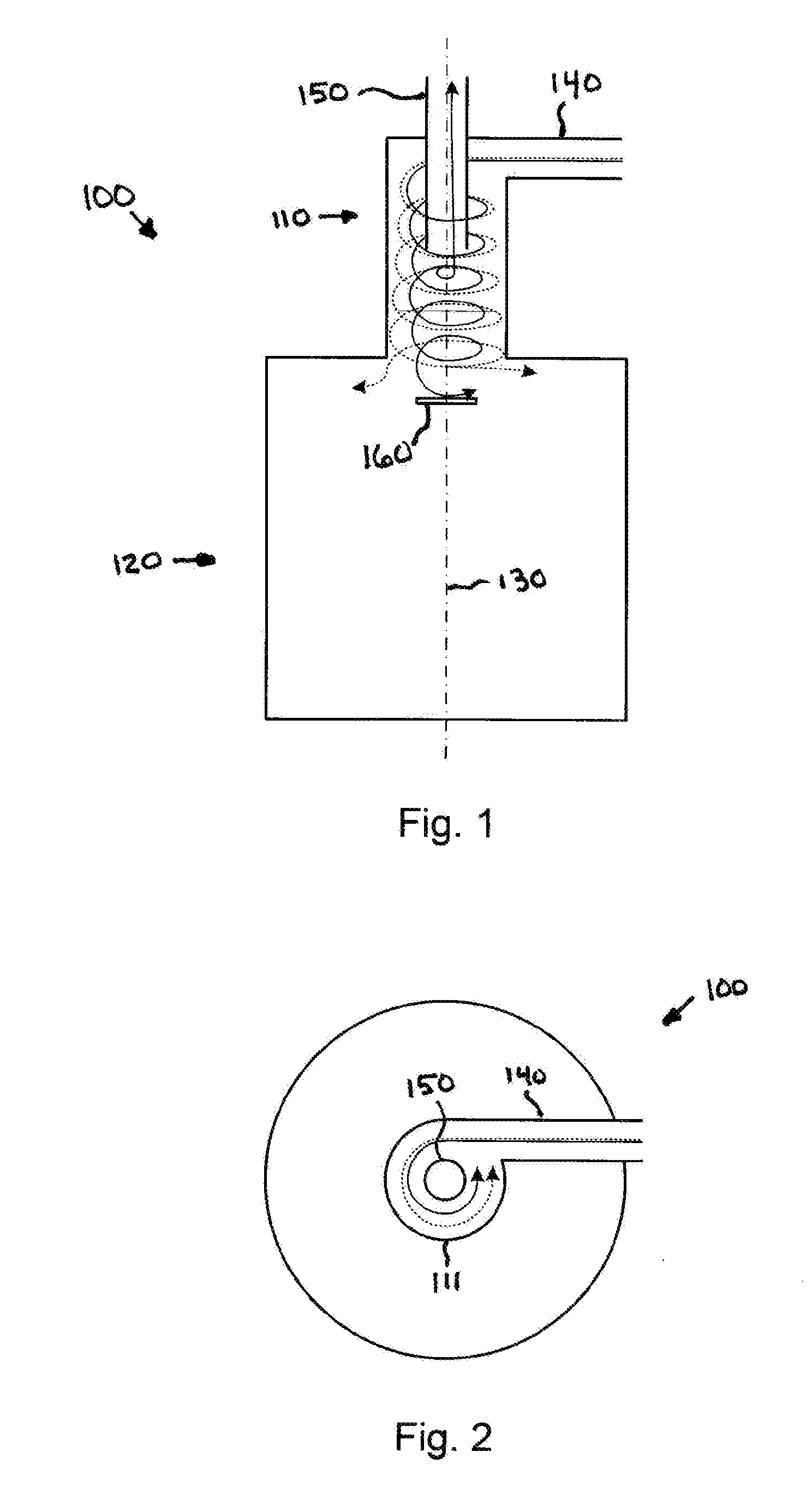
[0025]As described herein, various embodiments of the invention comprise systems and methods for removing sand and other solids that are suspended in fluids produced from wells. The present systems and methods introduce the fluids into a small separation chamber at a high speed and at an orientation that causes the fluid to circulate in a generally circular (e.g., helical) pattern within the chamber. This causes the solids suspended in the fluid to be urged away from the center of the chamber and toward the outer wall of the chamber. Fluid that is substantially free of suspended solids is then removed from the center of the chamber, while the solids settle and fall into an accumulation chamber that is positioned below the separation chamber.

[0026]One embodime...


PUM

PropertyMeasurementUnit
angleaaaaaaaaaa
angleaaaaaaaaaa
taper anglesaaaaaaaaaa

Abstract

Systems and methods for separating sand and other solids from oil and other fluids produced from a well. The present systems and methods introduce the fluids at relatively high speed into a generally cylindrical separation chamber. The fluids flow in a generally circular path within the chamber, causing the solids and higher density fluid / media to be urged outward from the axis of the chamber as the fluids flow from the upper portion of the chamber. Because the solids become concentrated at the outer wall of the chamber, the fluid in a central portion of the chamber is substantially free of the solids, and can be removed from the chamber via a fluid outlet. The solids concentrated at the outer wall of the chamber continue to move downward into an accumulation chamber in which the fluid speed is reduced, allowing the solids to settle out of the fluid.

Description

BACKGROUND[0001]1. Field of the Invention[0002]The invention relates generally to the production of natural gas, oil and other fluids from wells, and more particularly to systems and methods for removing sand and other solids from these fluids.[0003]2. Related Art[0004]Often, in the production of oil from wells, the oil is mixed with other, unwanted substances. These unwanted substances may include fluids such as gas and water, or solids such as sand. Gas and water may be mixed with the oil in underground reservoirs or other geological formations, and may flow into the well. Sand is commonly introduced into the oil as a result of production operations which are designed to fracture oil-bearing formations and thereby allow the oil to flow into the well. This technique of fracturing oil-bearing formations may be referred to as fracturing or “fracking” the well.[0005]The well equipment which is used to produce oil from a well typically includes components that are designed to separate ...

Claims


Application Information

Patent Timeline
Patent Type & Authority Applications(United States)
IPC IPC(8): B04C5/04B04C5/08B01D17/038B04C5/14
CPCB01D17/0217E21B43/34B04C5/085B04C5/181B04C5/14B01D21/2411B01D21/267B01D2221/04B04C5/185E21B43/35
Inventor HOWARD, ERIK M.
Owner TAPER LOK
Why Eureka
Try Eureka