Image Forming Apparatus

a technology of image forming apparatus and forming chamber, which is applied in the direction of thin material processing, article separation, transportation and packaging, etc., can solve the problems of increasing the manufacturing cost of generating abnormal clattering sound, and increasing so as to increase the manufacturing cost of the image forming apparatus, increase the manufacturing cost of the components, and prevent the occurrence of abnormal clattering sound

Active Publication Date: 2013-05-30
BROTHER KOGYO KK
View PDF0 Cites 8 Cited by
  • Summary
  • Abstract
  • Description
  • Claims
  • Application Information

AI Technical Summary

Benefits of technology

[0013]However, the strictly-managed manufacturing processes for the components such as the contact portion, the latching member, and the latchet gear might lead to increased manufacturing costs of the components. Consequently, it might result in an increased manufacturing cost of the image forming apparatus.
[0014]Aspects of the present invention are advantageous to provide one or more improved techniques for an image forming apparatus that make it possible to prevent occurrence of an abnormal sound by separating a latching member from a latchet gear at an appropriate moment and avoid a rise in the manufacturing cost of the image forming apparatus.

Problems solved by technology

Then, when a tooth portion of the latchet gear collides against the latching member, an abnormal clattery sound is generated.
However, the strictly-managed manufacturing processes for the components such as the contact portion, the latching member, and the latchet gear might lead to increased manufacturing costs of the components.
Consequently, it might result in an increased manufacturing cost of the image forming apparatus.

Method used


Image

  • Image Forming Apparatus
  • Image Forming Apparatus
  • Image Forming Apparatus

Examples


Embodiment Construction

[0026]It is noted that various connections are set forth between elements in the following description. It is noted that these connections in general and, unless specified otherwise, may be direct or indirect and that this specification is not intended to be limiting in this respect.

[0027]Hereinafter, an embodiment according to aspects of the present invention will be described with reference to the accompanying drawings. It is noted that, in the embodiment, aspects of the present invention are applied to an electrophotographic image forming apparatus.

[0028]1. Overall Configuration of Image Forming Apparatus

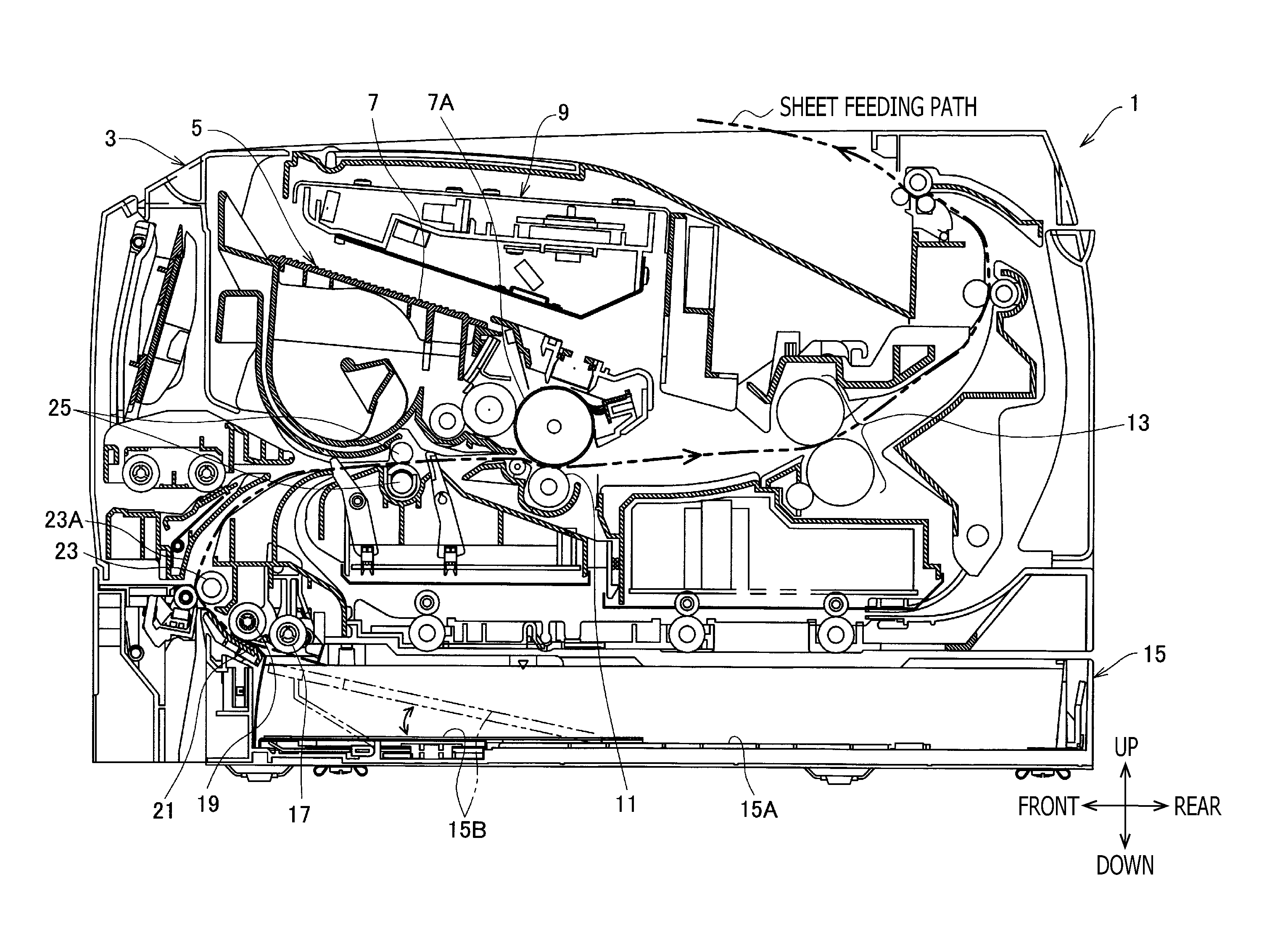
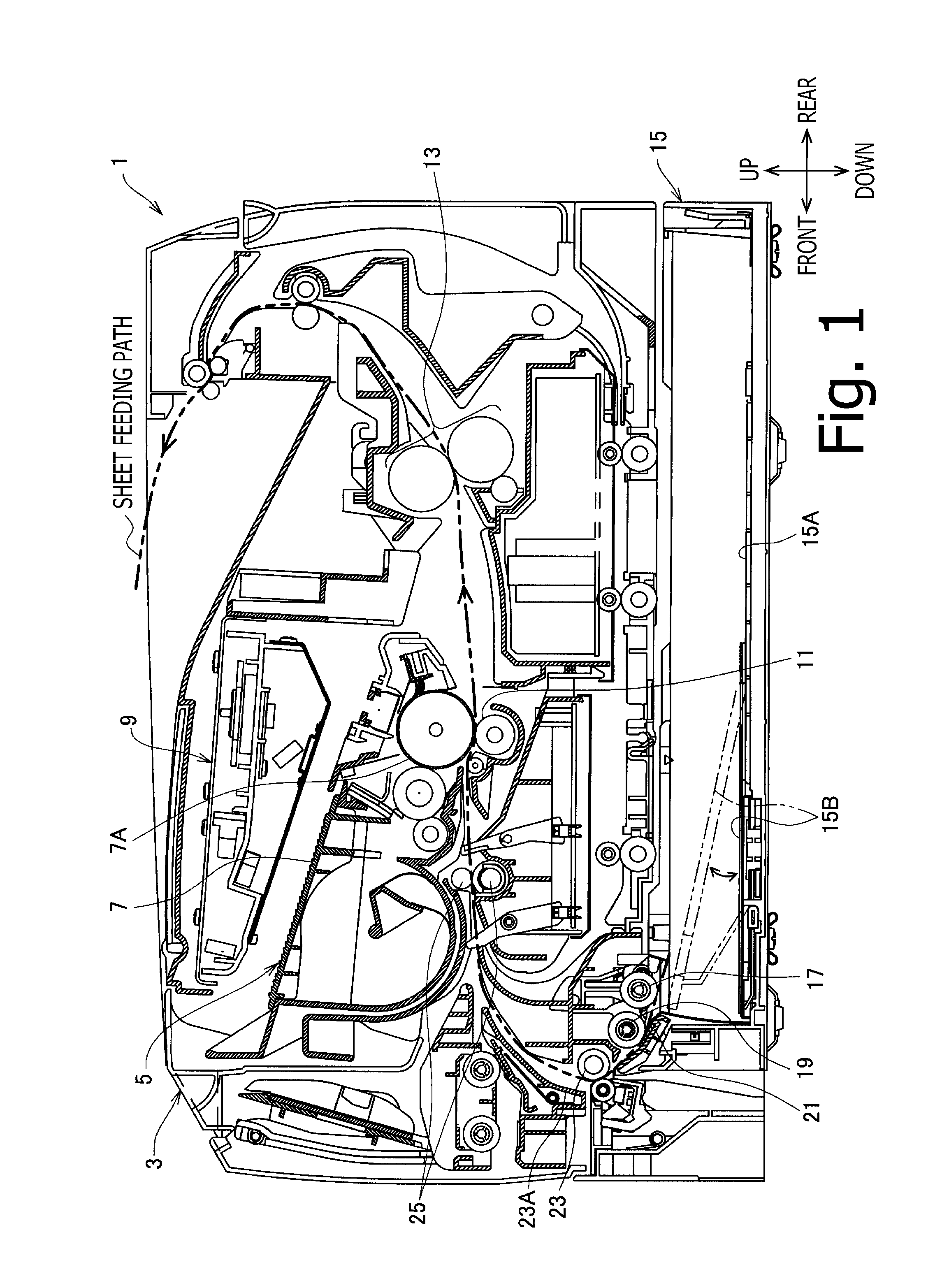
[0029]As shown in FIG. 1, an image forming apparatus 1 includes, in a housing 3 thereof, a monochrome image forming unit 5 configured to form an image on a sheet such as a recording sheet and a transparency by transferring a developer image onto the sheet.

[0030]The image forming unit 5 includes a process cartridge 7 that forms a development unit, an exposure unit 9 configured to ...


PUM


Abstract

An image forming apparatus is provided that includes a swing member swinging between a first position where a force for moving a pressing plate upward is transmitted to the pressing plate and a second position where transmission of the force is interrupted, a latchet mechanism that forbids the pressing plate to move downward and includes a latchet gear rotating in conjunction with a motion of the pressing plate and a latching member that is movably attached to the swing member and configured to forbid rotation of the latchet gear by engaging with the latchet gear, and a pressing member that applies a pressing force to the latching member when the swing member is in the second position and does not apply the pressing force to the latching member, and render the latching member movable relative to the swing member when the swing member is in the first position.

Description

Cross-Reference to Related Application[0001]This application claims priority under 35 U.S.C. §119 from Japanese Patent Application No. 2011-256501 filed on Nov. 24, 2011. The entire subject matter of the application is incorporated herein by reference.BACKGROUND [0002]1. Technical Field[0003]The following description relates to one or more techniques for an image forming apparatus having a function to sequentially feed a plurality of sheets placed on a loading unit such as a sheet tray.[0004]2. Related Art[0005]An image forming apparatus has been known that is provided with a pickup roller disposed above a feed tray and configured to prevent a lowered contact surface pressure between the pickup roller and sheets left on the feed tray by lifting a pressing plate in response to reduction in the number of the sheets left on the feed tray.[0006]Further, the known image forming apparatus is configured to switch a power transmission state between a state where a force for lifting the pres...

Claims


Application Information

Patent Timeline
Patent Type & Authority Applications(United States)
IPC IPC(8): B65H1/08
CPCB65H3/0669B65H2403/47B65H1/14B65H2403/72
Inventor AKATSUKA, YASUNORIARATACHI, TOMITAKE
Owner BROTHER KOGYO KK
Why Eureka
Try Eureka