Electrostatic induction power generator

a technology of induction power generator and induction power, which is applied in the direction of electrostatic generator/motor, influence generator, electrical apparatus, etc., can solve the problems of large error propagation to the distance that time and cost, and affects power generation performance, etc., to achieve the effect of improving the accuracy of the distance between the surfaces

Active Publication Date: 2013-05-30
ORMON CORP
View PDF6 Cites 11 Cited by
  • Summary
  • Abstract
  • Description
  • Claims
  • Application Information

AI Technical Summary

Benefits of technology

[0012]One or more embodiments of the present invention provide an electrostatic induction power generator which can easily improve the accuracy of a distance between surfaces of a pair of substrates facing each other.
[0023]According to one or more embodiments of the present invention, a dimensional error that affects the accuracy of the distance between the surfaces of the first substrate and the second substrate facing each other can be reduced to only a dimensional error of the regulating member and a dimensional error of the housing. Thereby, it is possible to eliminate effects of a dimensional error of the thickness of the substrates, which affects the distance between the surfaces of the first substrate and the second substrate facing each other.
[0025]Thereby, it is possible to smoothly move a substrate that moves (the other substrate) while maintaining a constant distance between the surfaces of the first substrate and the second substrate facing each other.
[0028]Thereby, it is possible to reduce sliding resistance of the regulating member (rotatable member).
[0032]As described above, according to one or more embodiments of the present invention, it is possible to easily improve the accuracy of the distance between the surfaces of a pair of substrates facing each other.

Problems solved by technology

However, as described above, the power generation performance is affected by the distance between the electret and a pair of electrodes in a direction in which the pair of substrates face each other.
Therefore, in the conventional example described above, the error propagation to the distance that affects the power generation performance is large.
Therefore, in the conventional example described above, the dimensional error of the thickness of the first substrate 220 affects the accuracy of the distance between the surfaces of the pair of substrates facing each other, so that it takes time and cost to adjust the distance.

Method used


Image

  • Electrostatic induction power generator
  • Electrostatic induction power generator
  • Electrostatic induction power generator

Examples


embodiment 1

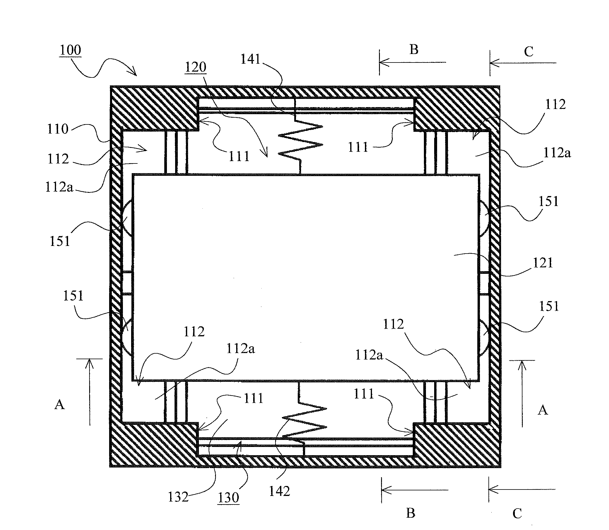
[0046]An electrostatic induction power generator according to Embodiment 1 of the present invention will be described with reference to FIGS. 1 to 7.

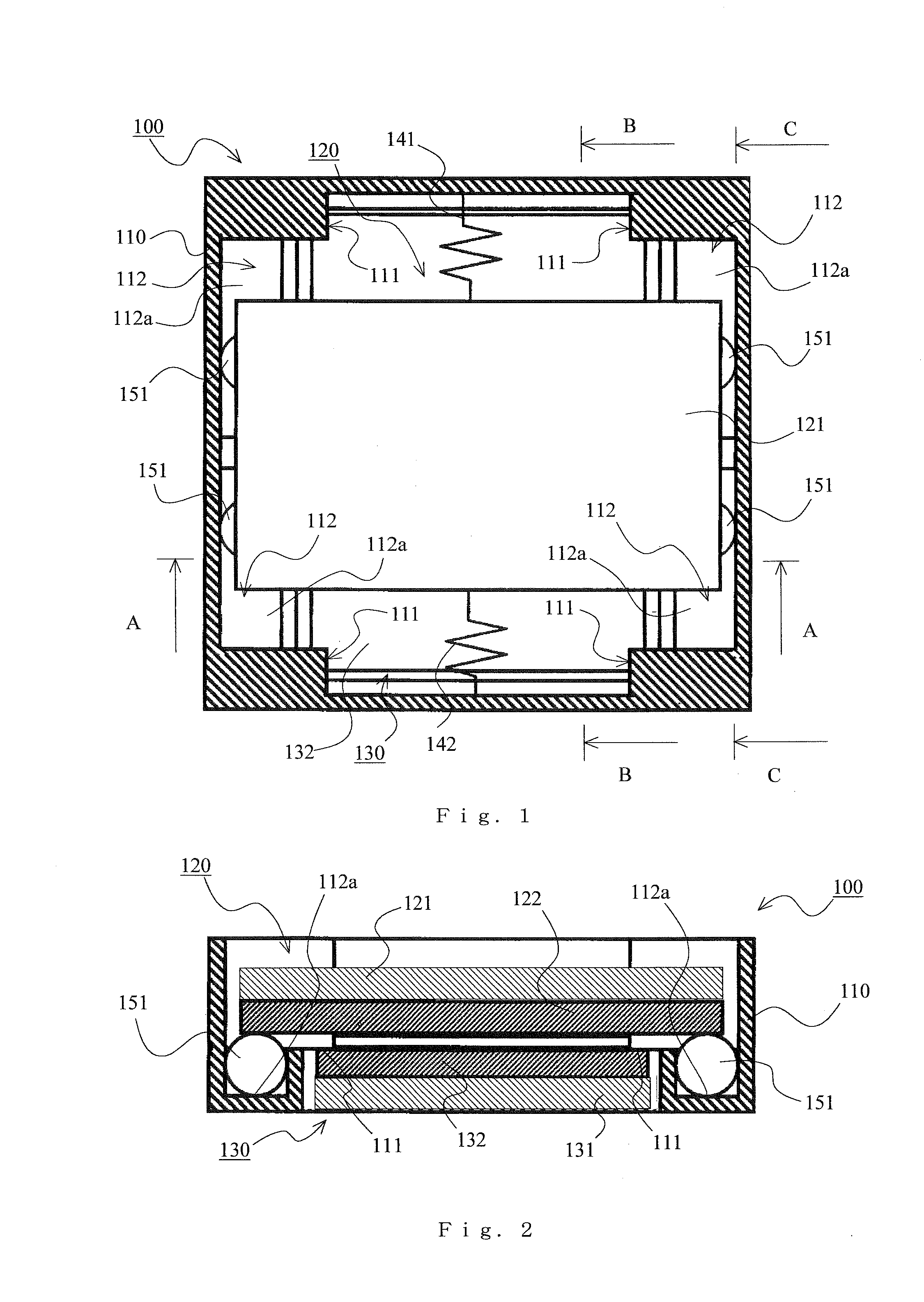
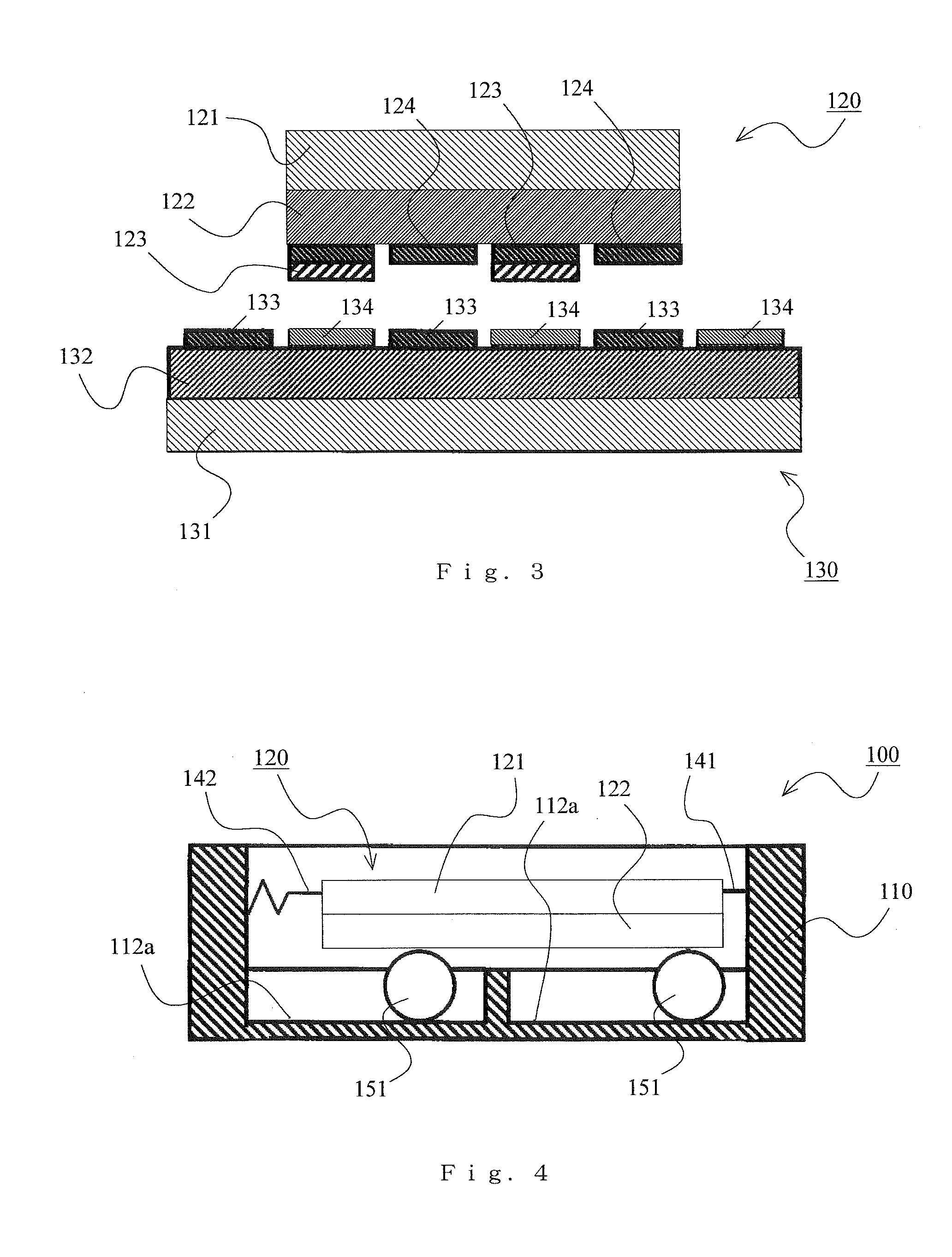
[0047]In particular, an overall configuration of the electrostatic induction power generator according to Embodiment 1 of the present invention will be described with reference to FIGS. 1 to 4. FIG. 1 is a schematic cross-sectional view of the electrostatic induction power generator according to the present embodiment. FIG. 1 is a view of the inside of the power generator as seen from the top. FIG. 2 is a schematic cross-sectional view of the electrostatic induction power generator according to the present embodiment. FIG. 2 is a cross-sectional view taken along a line A-A in FIG. 1. FIG. 3 is a schematic cross-sectional view of major components of the electrostatic induction power generator according to the present embodiment. FIG. 3 is a cross-sectional view taken along a line B-B in FIG. 1 (except for a housing and the like). FIG. 4 ...

embodiment 2

[0076]FIGS. 8 and 9 show Embodiment 2 of the present invention. Although, in Embodiment 1 described above, a configuration is described in which the spherical member, which is a rotatable member functioning as a regulating member, rolls along the guide groove, in the present embodiment, a configuration in which the spherical member rotates at a fixed position and does not roll will be described. The other components and functions are the same as those of Embodiment 1, so that the same reference numerals and symbols are given to the same components and the descriptions thereof will be omitted.

[0077]FIG. 8 is a schematic cross-sectional view of the electrostatic induction power generator according to the present embodiment. FIG. 8 is a view of the inside of the power generator as seen from the top. FIG. 9 is an enlarged cross-sectional view near the spherical member of the electrostatic induction power generator according to the present embodiment. FIG. 9 shows a cross section in para...

embodiment 3

[0081]FIGS. 10 and 11 show Embodiment 3 of the present invention. Although, in Embodiment 1 described above, a case is described in which the rotatable member functioning as a regulating member is the spherical member, in the present embodiment, a case will be described in which the rotatable member is a roller. The other components and functions are the same as those of Embodiment 1, so that the same reference numerals and symbols are given to the same components and the descriptions thereof will be omitted.

[0082]FIG. 10 is a schematic cross-sectional view of the electrostatic induction power generator according to the present embodiment. FIG. 10 is a view of the inside of the power generator as seen from the top. FIG. 11 is a schematic cross-sectional view of the electrostatic induction power generator according to the present embodiment. FIG. 11 is a cross-sectional view taken along a line A-A in FIG. 10.

[0083]In the present embodiment, the rotatable member functioning as a regul...


PUM


Abstract

An electrostatic induction power generator includes a spherical member for making a distance between surfaces of a first substrate and a second substrate facing each other constant. A housing is provided with a first reference surface to which a surface of the second substrate facing the first substrate is fixed and which is a positioning reference for the second substrate with respect to the surface facing the first substrate in a vertical direction, and a second reference surface with which the spherical member is slidably in contact and which is a positioning reference for the spherical member with respect to the surface facing the first substrate in the vertical direction. The spherical member is slidably in contact with a surface of the first substrate facing the second substrate.

Description

TECHNICAL FIELD[0001]The present invention relates to an electrostatic induction power generator that can be used as a vibration power generator or the like for generating power using ambient vibration.BACKGROUND ART[0002]Conventionally, an electrostatic induction power generator is known in which a pair of substrates configured to be able to reciprocate relative to each other while maintaining a state in which the substrates face each other are provided, a plurality of electrets are arranged in a row on one of the pair of substrates, and a plurality of pairs of electrodes are arranged in a row on the other one of the pair of substrates. According to the electrostatic induction power generator, when the pair of substrates move relative to each other, an electrostatic capacitance between one electrode of a pair of electrodes and the electret changes and also an electrostatic capacitance between the other electrode of a pair of electrodes and the electret changes, so that a difference...

Claims


Application Information

Patent Timeline
Patent Type & Authority Applications(United States)
IPC IPC(8): H02N1/08
CPCH02N1/08H02N1/00
Inventor IKUTA, MASAYOSAKURAI, KENJIOKADA, WATARU
Owner ORMON CORP
Why Eureka
Try Eureka