Turbomachine rotor with blade roots with adjusting protrusions

a technology of blade roots and rotors, which is applied in the direction of liquid fuel engines, vessel construction, marine propulsion, etc., can solve the problems of affecting the ability to accurately control the tip clearance to the casing

Inactive Publication Date: 2013-08-01
SIEMENS AG
View PDF4 Cites 5 Cited by
  • Summary
  • Abstract
  • Description
  • Claims
  • Application Information

AI Technical Summary

Benefits of technology

[0007]This aspect of the invention is based on the idea that a fine adjustment of the root dimension is easier and faster if not a full surface but only a protrusion structure of the root has to be machined or trimmed.
[0029]According to a further embodiment, the method further comprises machining a radially outer portion of the rotor blade after mounting the rotor blade to the rotation element. Having adjusted the maximum clearance between the stop face and the rotation element to a desired, specific value, machining of a tip portion of the rotor blade can be performed so as to achieve a high accuracy of the distance between the rotor blade and a turbomachine casing that surrounds the turbomachine rotor with the rotor blade.

Problems solved by technology

The inventor found that a large variation between the two conditions may hinder the ability to accurately control the desired tip clearance to the casing.

Method used


Image

  • Turbomachine rotor with blade roots with adjusting protrusions
  • Turbomachine rotor with blade roots with adjusting protrusions
  • Turbomachine rotor with blade roots with adjusting protrusions

Examples


Embodiment Construction

[0038]The illustration in the drawings is schematic. It is noted that in different figures, similar or identical elements are provided with the same reference signs or with reference signs, which are different from the corresponding reference signs only within the first digit. The description of such elements is not repeated. Rather only differences between different figures are emphasized.

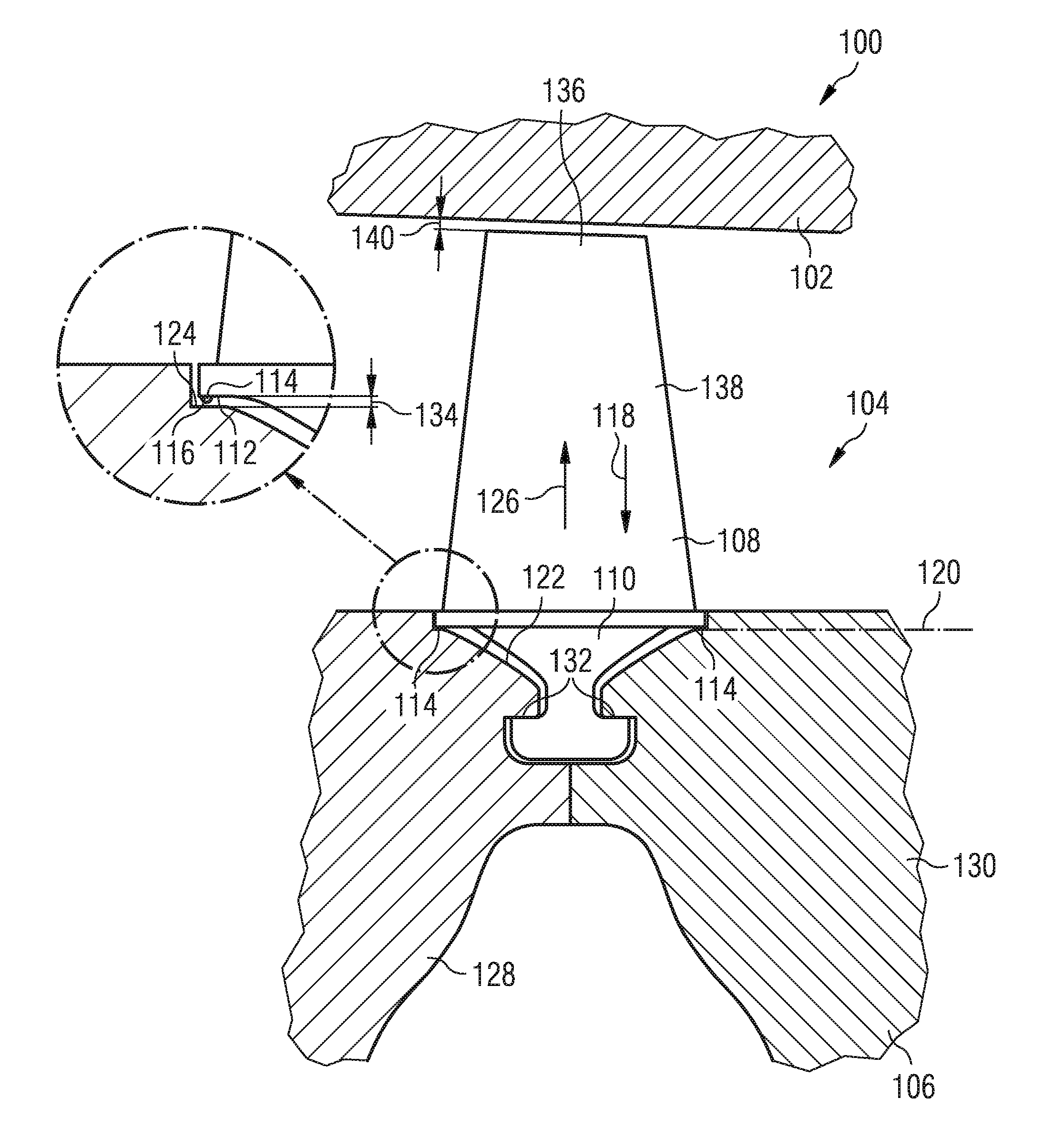
[0039]FIG. 1 shows a cross sectional view of part of a compressor of a gas turbine 100 in accordance with embodiments of the herein disclosed subject matter. In accordance with an embodiment, the compressor section of gas turbine 100 comprises a casing 102 and a rotor 104. The rotor comprises a rotation element 106 and a rotor blade 108. The rotor blade 108 comprises a root 110 for mounting the rotor blade 108 to the rotation element 106 of the gas turbine 100. In accordance with an embodiment, the root comprises a protrusion structure 114 and a base portion 112 located laterally adjacent the prot...


PUM

PropertyMeasurementUnit
angleaaaaaaaaaa
angleaaaaaaaaaa
curvatureaaaaaaaaaa

Abstract

A turbomachine rotor includes a rotor blade mounted to a rotation element. The rotor blade includes a root for mounting the rotor blade to the rotation element. The root has a protrusion structure forming a stop face supporting the mounted root against the rotation element under action of a radially inwardly directed force. The protrusion structure defines a maximum clearance between the stop face and the rotation element. The root is radially moveable to a certain extent where in a radially outermost position the protrusion structure has the maximum radial clearance from the rotation element. The rotation element includes a groove therein. The groove has a groove face bearing the stop face of the rotor blade under action of a radially inwardly directed force. The groove is a circumferential groove extending in a circumferential direction with regard to an axis of rotation of the rotation element.

Description

FIELD OF INVENTION[0001]The present invention relates to the field of turbomachines, and the assembly of bladed rotors.ART BACKGROUND[0002]EP 0 757 749 B1 relates to gas turbine engines. A pair of root rails is provided on the bottom of a dovetail-shaped root portion of a gas turbine engine blade to minimize reciprocating tangential motion of the blades within the dovetail shaped slots in which the root portions of the blades are retained. Each root rail is wedge shaped, tapering in a decreasing cross section from the base of the root toward the aerofoil platform.[0003]In view of the above-described situation, there exists a need for an improved technique that enables to provide for an efficient assembly of a turbomachine.SUMMARY OF THE INVENTION[0004]This need may be met by the subject matter according to the independent claims. Advantageous embodiments of the herein disclosed subject matter are described by the dependent claims.[0005]The inventor found that is beneficial to allow ...

Claims


Application Information

Patent Timeline
Patent Type & Authority Applications(United States)
IPC IPC(8): F01D5/30
CPCF01D5/005F01D5/3007F05D2230/60F05D2240/80Y10T29/49316F01D5/30F04D19/02F04D29/322F05D2250/70
Inventor MILNE, TREVOR
Owner SIEMENS AG
Why Eureka
Try Eureka