
Driving apparatus for light emitting diode and control method thereof

a technology of light-emitting diodes and driving apparatuses, which is applied in the direction of instruments, light sources, electroluminescent light sources, etc., can solve the problems of increasing circuit area and manufacturing costs, only ever using related art lighting, and having more complex and varied functions

Inactive Publication Date: 2013-05-30
SAMSUNG ELECTRO MECHANICS CO LTD +1
View PDF2 Cites 13 Cited by
  • Summary
  • Abstract
  • Description
  • Claims
  • Application Information

AI Technical Summary

Benefits of technology

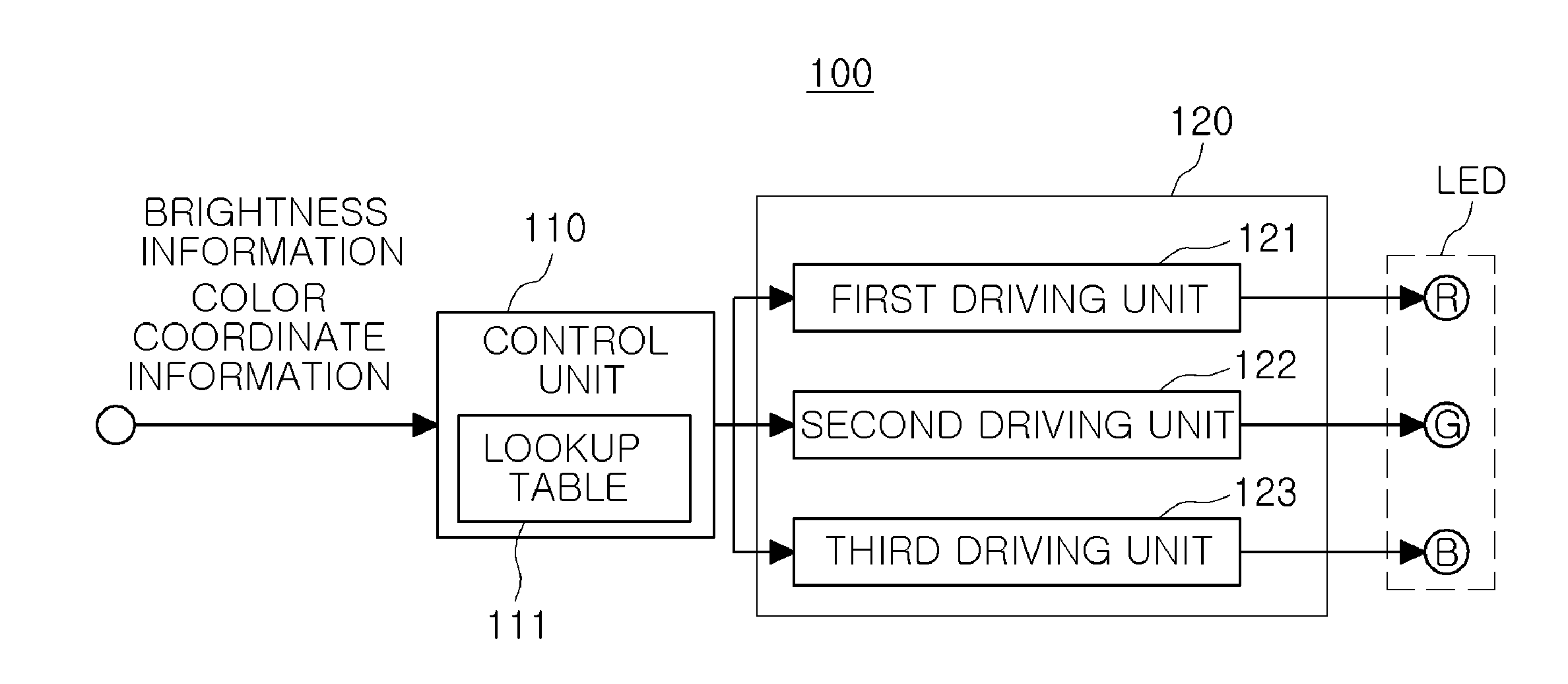
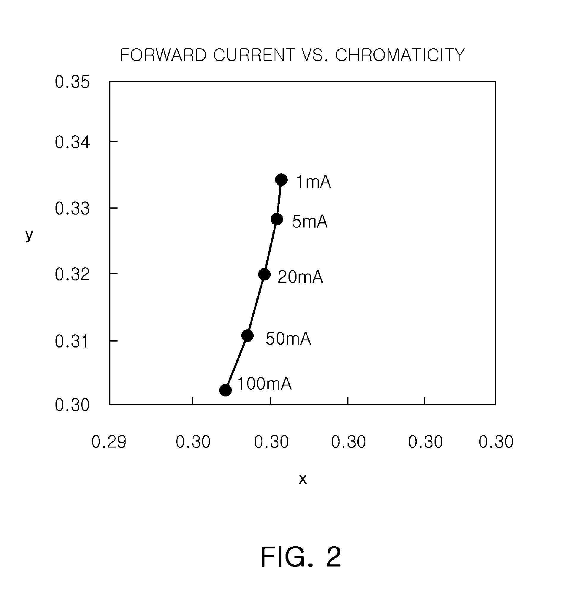
The patent provides a driving apparatus for LED that can emit light of a desired color by adjusting the input color coordinate value based on the input brightness value. When the brightness value is equal to or greater than a preset reference brightness value, the x-color coordinate value of the red LED may be increased, and the y-color coordinate value of the red LED may be decreased. Similarly, when the brightness value is equal to or greater than a preset reference brightness value, the x-color coordinate value of the green LED may be decreased, and the y-color coordinate value of the green LED may be increased. The same applies for the blue LED, wherein when the brightness value is equal to or greater than a preset reference brightness value, the x-color coordinate value of the blue LED may be increased, and the y-color coordinate value of the blue LED may be decreased. This invention allows for accurate and efficient control of LED light emission for various lighting and display applications.

Problems solved by technology

Due to the fact that an LED lighting apparatus can be manufactured to have a compact size, an LED lighting apparatus may be used even in a place in which it is difficult to install an existing lighting apparatus.
Meanwhile, related art lighting has only ever been used for the purpose of simply emitting light, or providing information.
However, with improvements in the quality of life, driving apparatuses having more complex and varied functions have been developed for the purpose of user conveniences, consumer demand, and the like.
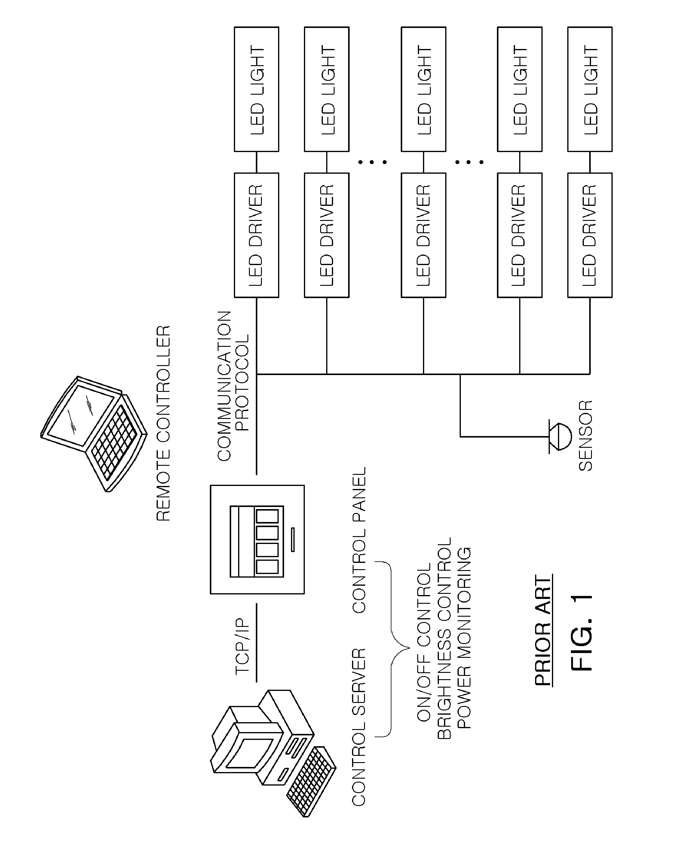
In order to solve these problems, a feedback system or a sensing circuit is added in the related art; however, this may cause other problems in terms of an increased circuit area and increased manufacturing costs.

Method used


Image

  • Driving apparatus for light emitting diode and control method thereof
  • Driving apparatus for light emitting diode and control method thereof
  • Driving apparatus for light emitting diode and control method thereof

Examples


Embodiment Construction

[0030]Hereinafter, embodiments will be described in detail with reference to the accompanying drawings so that they can be easily practiced by those skilled in the art to which the present invention pertains.

[0031]However, in describing embodiments of the present invention, detailed descriptions of well-known functions or constructions will be omitted so as not to obscure the description of the present invention with unnecessary detail.

[0032]In addition, like reference numerals denote parts performing similar functions and actions throughout the drawings.

[0033]In addition, in a whole disclosure, when one element is referred to as being “connected” to another element, it should be understood that the former can be “directly connected” to the latter, or “indirectly connected” to the latter via an intervening element.

[0034]Unless explicitly described to the contrary, the word “comprise” and variations such as “comprises” or “comprising,” will be understood to imply the inclusion of sta...


PUM


Abstract

There are provided a driving apparatus for a light emitting diode (LED) which may accurately display a desired color of light by adjusting a color coordinate value in accordance with an input brightness value, and a control method thereof. The driving apparatus includes a control unit receiving a brightness value and a color coordinate value of an LED desired to be controlled and controlling LED driving by adjusting the color coordinate value in accordance with the received brightness value; and a driving unit driving the LED in accordance with controlling of the control unit.

Description

CROSS-REFERENCE TO RELATED APPLICATIONS[0001]This application claims the priority of Korean Patent Application No. 10-2011-0125074 filed on Nov. 28, 2011, in the Korean Intellectual Property Office, the disclosure of which is incorporated herein by reference.BACKGROUND OF THE INVENTION[0002]1. Field of the Invention[0003]The present invention relates to a driving apparatus for a light emitting diode (LED) that may control color illumination in accordance with an input color coordinate value and an input brightness value, and a control method thereof.[0004]2. Description of the Related Art[0005]In recent years, interest in and demand for light emitting diode (LED) lighting apparatuses have increased.[0006]Due to the fact that an LED lighting apparatus can be manufactured to have a compact size, an LED lighting apparatus may be used even in a place in which it is difficult to install an existing lighting apparatus. In addition, the implementation of various colors and adjustment of th...

Claims


Application Information

Patent Timeline
Patent Type & Authority Applications(United States)
IPC IPC(8): H05B37/02
CPCH05B33/086H05B37/0254H05B33/0869H05B45/22H05B45/20H05B47/18H05B45/46H05B45/37
Inventor PARK, CHAN WOOCHA, SANG HYUNYOO, SE HOONLEE, JONG WOOKIM, KI CHULGONG, JUNG CHULLEE, JAE SHIN
Owner SAMSUNG ELECTRO MECHANICS CO LTD
Learn More