Image forming apparatus

a technology of image forming apparatus and forming tube, which is applied in the direction of electrographic process apparatus, instruments, optics, etc., can solve the problems of low transferability of toner, image defects such as dropouts and blank spots, and leakage at places

Active Publication Date: 2013-05-30
RICOH KK
View PDF8 Cites 42 Cited by
  • Summary
  • Abstract
  • Description
  • Claims
  • Application Information

AI Technical Summary

Benefits of technology

[0012]In view of the foregoing, in an aspect of this disclosure, there is provided an improved image forming apparatus including an image bearing member, a transfer device, and a controller. The image bearing member bears a toner image on an image bearing surface thereof. The transfer device transfers the toner image on the image bearing surface onto a recording medium using a transfer electric field. The controller includes a CPU to change the transfer electric field and a transfer speed for transferring the toner image from the image bearing member onto the recording medium. The transfer device includes a power source, a first electrode, and a second electrode. The power source outputs a superimposed bias in which an AC voltage is

Problems solved by technology

As a result, the toner is not transferred sufficiently onto the recessed portions, causing low transferability of toner and hence resulting in image defects such as dropouts and blank spots.
As a result, leakage occurs at places such as an end portion of a transfer device (for example, a transfer roller) constituting the transfer nip, an insulating member that insulates from a housing an electrode

Method used


Image

  • Image forming apparatus
  • Image forming apparatus
  • Image forming apparatus

Examples


embodiment 1

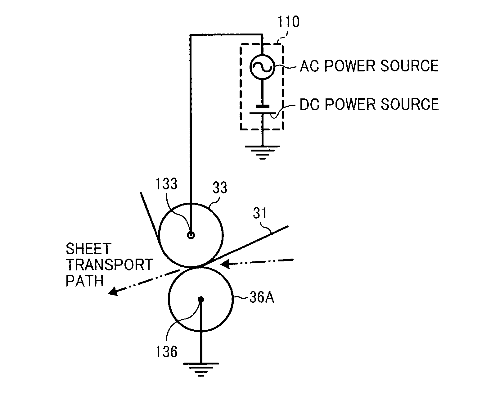
[0098]With reference to FIG. 4, a description is provided of the transfer device employing the secondary transfer device 36 according to a first illustrative embodiment (EMBODIMENT 1) of the present invention. According to the present illustrative embodiment, the secondary transfer device 36 includes the secondary transfer roller 36A facing the transfer auxiliary roller 33 via the transfer belt 31.

[0099]As illustrated in FIG. 4, according to the present illustrative embodiment, the superimposed bias power source 110 applies a bias to a cored metal shaft of the transfer auxiliary roller 33 which contacts the inner surface of the transfer belt 31 which is a surface opposite an image bearing surface onto which the toner image is transferred. More specifically, the superimposed bias power source 110 includes the AC power source under constant voltage control and the DC power source under constant current control. The superimposed bias power source 110 applies the transfer auxiliary roll...

embodiment 2

[0120]With reference to FIG. 5, a description is provided of a second illustrative embodiment (EMBODIMENT 2). According to the present illustrative embodiment, the configuration of the power source is different from that of EMBODIMENT 1.

[0121]According to the present illustrative embodiment, a first DC power source 111 is under constant current control, and the maximum output voltage thereof is 10 kV and does not exceed the leakage limit of approximately 12 kV.

[0122]A superimposed bias power source 110′ includes a second DC power source 110A and an AC power source 110B. The second DC power source 110A is under constant current control, and the maximum output voltage thereof is 5 kV. The AC power source 110B is under constant voltage control, and the maximum output peak-to-peak voltage is 10 kV.

[0123]As the superimposed bias power source, the maximum peak voltage is 10 kV. Thus, the maximum output voltage of the AC power source 110B is configured to be less than the leakage limit of ...

embodiment 3

[0127]With reference to FIG. 6, a description is provided of a third illustrative embodiment of the present invention (EMBODIMENT 3). According to the present illustrative embodiment, the superimposed power source 110′ of the Embodiment 2 is employed to form a transfer electric field between the photosensitive drum 2 serving as an image bearing member, instead of the transfer belt 31, and the primary transfer roller 35 to transfer the toner image on the photosensitive drum 2 directly onto the recording medium. It is to be noted that suffixes Y, M, C, and K indicating the colors yellow, magenta, cyan, and black are omitted, unless otherwise specified.

[0128]The photosensitive drum 2 includes an aluminum base on which a photosensitive layer is laminated. The primary transfer roller 35 has a two-layer structure including a metal cored bar and a resistance layer. The resistance layer is made of rubber such as a copolymer (ion-conductive) of nitrile butadiene (NBR) and epichlorohydrin (EC...


PUM


Abstract

An image forming apparatus includes a controller and a transfer device including a power source to output a superimposed bias in which an AC voltage is superimposed on a DC voltage, a first electrode, a second electrode disposed opposite the first electrode with an image bearing member interposed therebetween to form a transfer electric field to transfer a toner image on the image bearing member to a recording medium. The controller including a CPU adjusts the transfer electric field and a transfer speed. One of the first electrode and the second electrode is connected to the power source, and the other is grounded. The controller adjusts the transfer speed such that in a case in which an oscillating electric field of the transfer electric field is strong, a maximum transfer speed is slower than the maximum transfer speed in a case in which the oscillating electric field is weak.

Description

CROSS-REFERENCE TO RELATED APPLICATIONS[0001]This patent application is based on and claims priority pursuant to 35 U.S.C. §119 from Japanese Patent Application Nos. 2011-261768, filed on Nov. 30, 2011, and 2012-167707, filed on Jul. 27, 2012, both in the Japan Patent Office, which are hereby incorporated herein by reference in their entirety.BACKGROUND OF THE INVENTION[0002]1. Field of the Invention[0003]Exemplary aspects of the present invention generally relate to an image forming apparatus, such as a copier, a facsimile machine, a printer, or a multi-functional system including a combination thereof, and more particularly to, a transfer device employed in the image forming apparatus.[0004]2. Description of the Related Art[0005]Known image forming apparatuses, such as copiers, facsimile machines, printers, or multifunction printers having at least one of copying, printing, scanning, and facsimile capabilities, typically form an image on a recording medium according to image data....

Claims


Application Information

Patent Timeline
IPC IPC(8): G03G15/16
CPCG03G15/18G03G15/5029G03G15/1675G03G15/1605
Inventor OGIYAMA, HIROMITAKEUCHI, TOMOKAZUSHIMIZU, YASUNOBUSENGOKU, KENJIHAGA, HIROYOSHITANAKA, SHINYA
Owner RICOH KK
Why Eureka
Try Eureka