Turbomachine casing assembly

a technology for turbines and casings, which is applied in the direction of machines/engines, mechanical devices, liquid fuel engines, etc., can solve the problems of not being able to simply strengthen, not being able to use swept fan blades, and not being strong enough along the forward region, so as to reduce the weight of the assembly, and facilitate the manufacture

Inactive Publication Date: 2013-05-30
ROLLS ROYCE PLC
View PDF1 Cites 19 Cited by
  • Summary
  • Abstract
  • Description
  • Claims
  • Application Information

AI Technical Summary

Benefits of technology

[0020]The casing assembly of the present invention allows a shed fan blade to penetrate the first casing element at a first, or forward, end, whilst remaining impervious to ice impact the opposite, or rear, end. The competing requirements of fan blade ice shedding loads and fan blade off loads may thus be accommodated in a way that was not previously possible. The manner in which this is achieved allows for the potential to tune the casing assembly to optimally fulfil each requirement whilst simultaneously saving weight and easing manufacture.
[0021]In addition, by forming a void within the casing assembly, the weight of the assembly can be reduced. This increases the weight efficiency of the engine and makes it more attractive for aircraft applications.

Problems solved by technology

It will therefore be shed from the blade tip and may strike the fan track liner forward of the ice impact panel.
A conventional fan track liner is generally not strong enough along its forward region to withstand ice impact and is therefore generally not suitable for use with swept fan blades.
It is not possible simply to strengthen the fan track liner to accommodate ice impact, because this may disrupt the blade trajectory during an FBO event, and thereby compromise the operation of the fan casing containment system.
This may result in undesirable, forward ejection of high kinetic energy debris through the engine intake.

Method used


Image

  • Turbomachine casing assembly
  • Turbomachine casing assembly
  • Turbomachine casing assembly

Examples


first embodiment

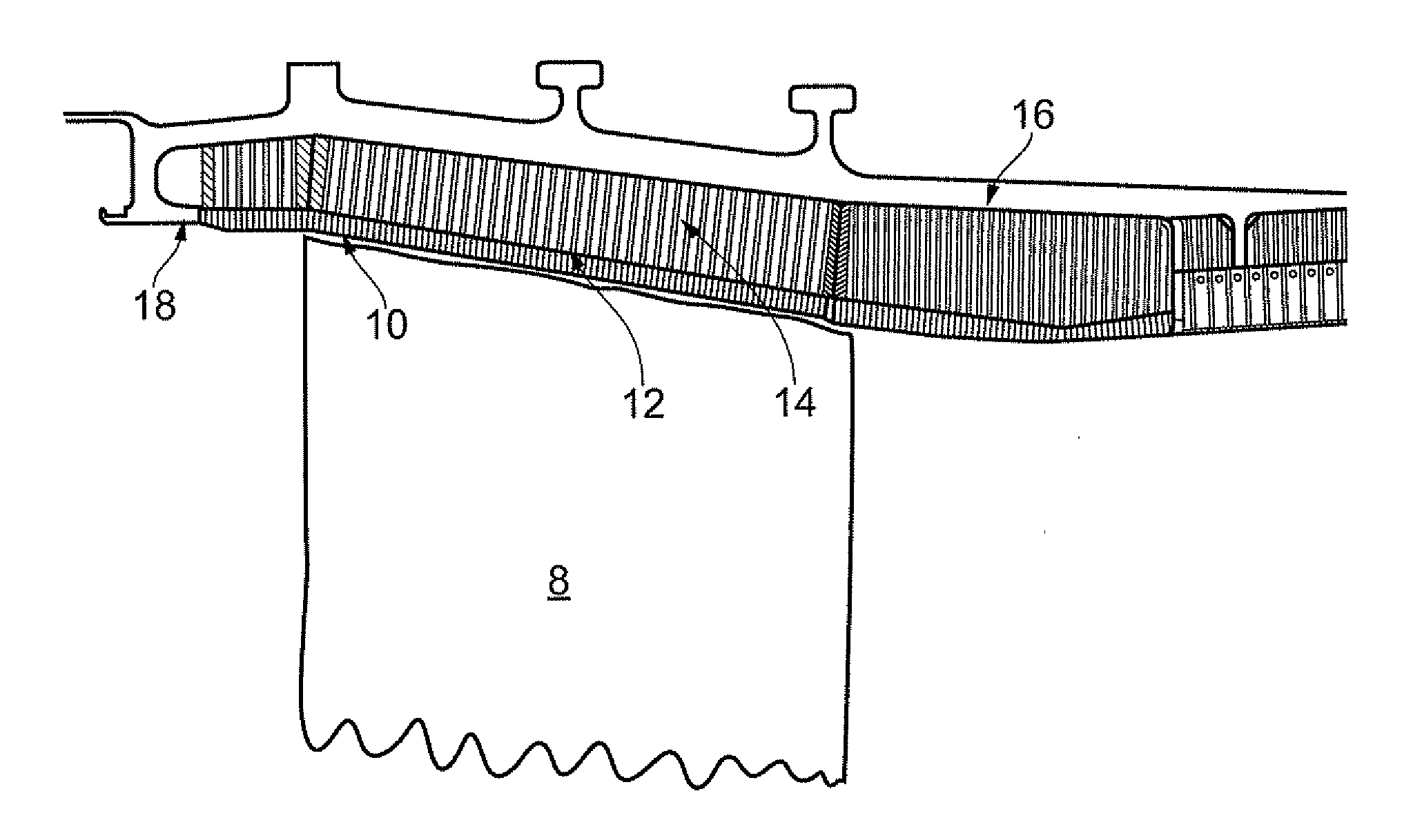
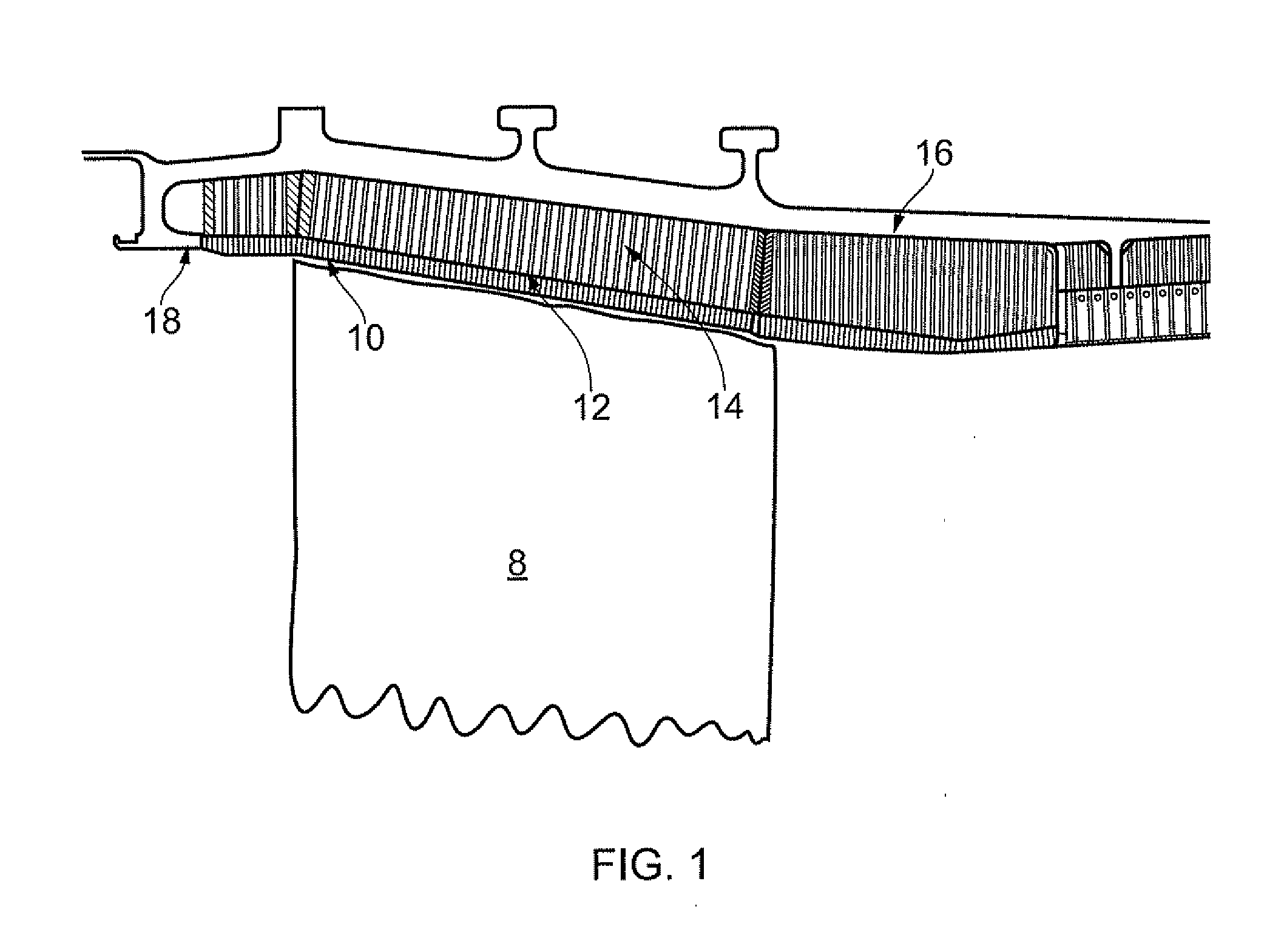
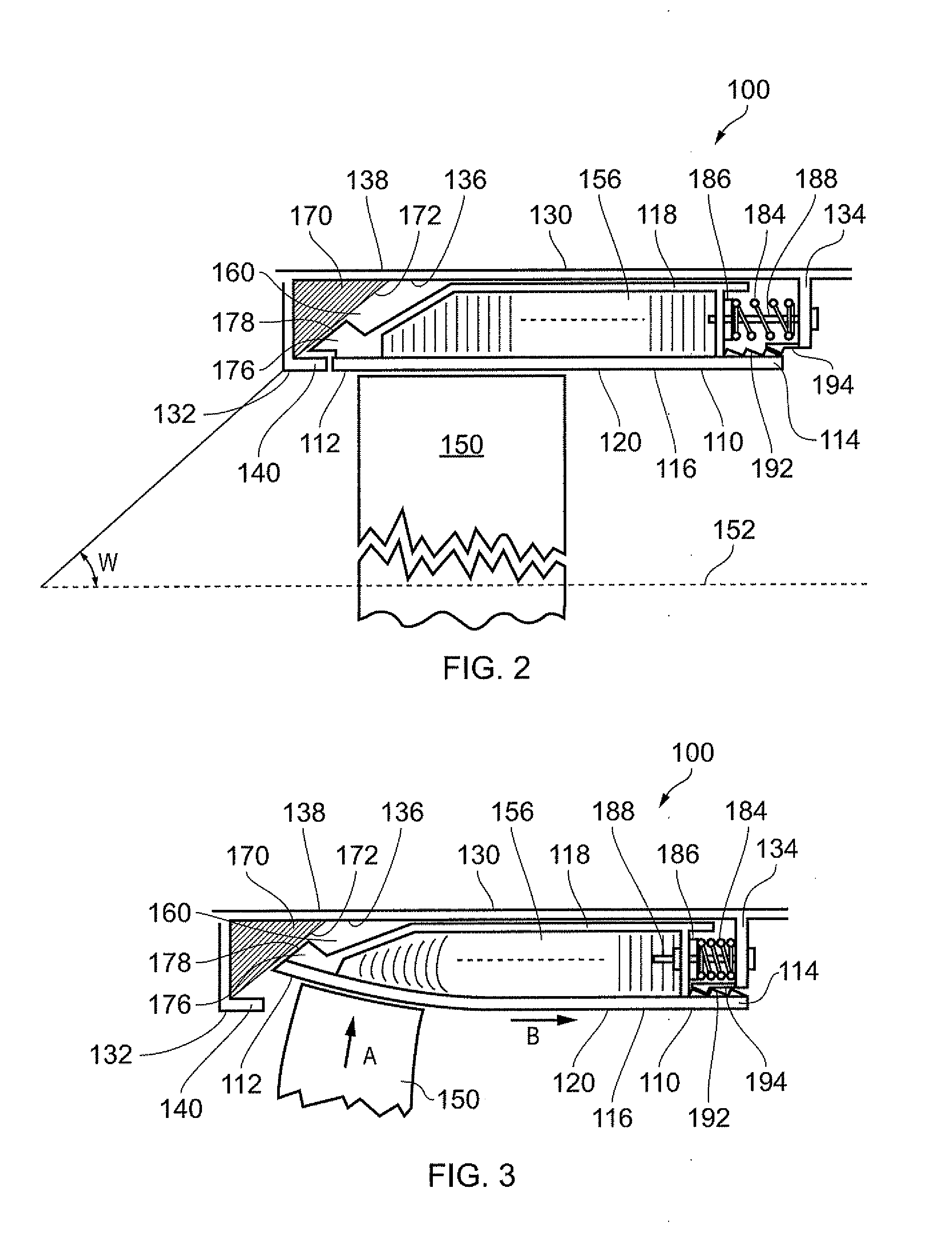
[0071]Referring to FIGS. 2 and 3, a fan casing assembly according to the invention is designated generally by the reference numeral 100 and comprises a first casing element 110 and a second casing element 130.

[0072]The first casing element 110 has a first end 112, a second end 114, a radially proximal face 116 and a radially distal face 118, and the second casing element 130 has a first end 132, a second end 134, a radially proximal face 136 and a radially distal face 138.

[0073]The first casing element 110 at least partially encloses one or more rotating aerofoil structures 150. These aerofoil structures 150 may comprise blades of a turbomachine, in particular compressor fan blades. The second casing element 130 is disposed radially distal to the first casing element 110.

[0074]The turbomachine casing assembly 100 comprises a plurality of first casing elements 110 circumferentially disposed about a curve defined by the blade tip path of the one or more aerofoil structures 150 of the ...

second embodiment

[0090]Referring to FIGS. 4 and 5, a fan casing assembly according to the invention is designated generally by the reference numeral 200. Features of the fan casing assembly 200 which correspond to those of fan casing assembly 100 have been given corresponding reference numerals for ease of reference.

[0091]The fan casing assembly 200 has a first casing element 210 and a second casing element 130.

[0092]In this embodiment, the first casing element 210 has a first end 212, a second end 214, a radially proximal face 216 and a radially distal face 218. The radially proximal face 216 comprises an abradable layer 120. The radially distal face 218 of the first casing element 210 corresponds to the radially proximal face 136 of the second casing element 130.

[0093]The radially proximal and distal faces 216,218 of the first casing element 210 are spaced apart from one another with an infill member 256 positioned therebetween.

[0094]A second interface portion 276 in the form of a convex protrusio...

third embodiment

[0098]Referring to FIG. 7, a fan casing assembly according to the invention is designated generally by the reference numeral 300. Features of the fan casing assembly 300 which correspond to those of fan casing assembly 100 have been given corresponding reference numerals for ease of reference.

[0099]The fan casing assembly 300 has a plurality of first casing elements 310 each comprising a first end 312, a second end 314 and a radially proximal face 316. The first casing elements 310 further comprise a first edge 318 and an opposite second edge 320; the first and second edges 318,320 each extending from the first end 312 to the second end 314.

[0100]Each of the first and second edges 318,320 comprises a respective first and second edge step 322,324 located at a mid-portion thereof. Each first edge step 322 on the first edge 318 of a first casing element 310 co-operates with the second edge step 324 on the second edge 320 of the adjoining first casing element 310.

[0101]FIG. 7 shows a pa...


PUM


Abstract

A turbomachine casing assembly includes a first casing element locatable radially outward of one or more rotating aerofoil elements of a turbomachine and a second casing element located radially distal to the first casing element, with a void being defined between the first and second casing elements. Each of the first and second casing elements includes, at a first end thereof, respective co-operating first and second interface portions. In the event that an aerofoil element becomes detached from the turbomachine and impacts the first casing element, the second interface portion; slides along the first interface portion and the first end of the first casing element enters the void.

Description

[0001]This invention claims the benefit of UK Patent Application No. 1120557.2, filed on 30 Nov. 2012, which is hereby incorporated herein in its entirety.FIELD OF THE INVENTION[0002]This invention relates to a turbomachine casing assembly and particularly, but not exclusively, to a casing assembly for the fan of a turbofan gas turbine engine.BACKGROUND[0003]Turbofan gas turbine engines for powering aircraft generally comprise inter alia a core engine, which drives a fan. The fan comprises a number of radially extending fan blades mounted on a fan rotor which is enclosed by a generally cylindrical fan casing.[0004]There is a remote possibility with such engines that part or all of a fan blade could become detached from the remainder of the fan, for example as a result of the engine ingesting a bird or other foreign object.[0005]It is known to provide the fan casing with a fan track liner which incorporates a containment system, designed to contain any released blades or associated d...

Claims


Application Information

Patent Timeline
Patent Type & Authority Applications(United States)
IPC IPC(8): F01D25/26
CPCF01D21/045F04D27/0292Y02T50/672F04D29/526Y02T50/60
Inventor EVANS, DALE EDWARD
Owner ROLLS ROYCE PLC
Why Eureka
Try Eureka