Liquid crystal display and driving method thereof

a technology of liquid crystal display and driving method, which is applied in the direction of instruments, static indicating devices, etc., can solve the problems of reducing the resolution of the data driving circuit b>10/b>, affecting and reducing the accuracy of the data driving circuit. achieve the effect of reducing power consumption and high resolution

Active Publication Date: 2013-06-06
LG DISPLAY CO LTD
View PDF2 Cites 46 Cited by
  • Summary
  • Abstract
  • Description
  • Claims
  • Application Information

AI Technical Summary

Benefits of technology

[0015]Accordingly, an aspect of the present invention is to provide a liquid crystal display which ensures a timing margin for DEMUX control signals even though a liquid crystal display panel has a high resolution, and has lower power consumption, and a driving method thereof.

Problems solved by technology

The data driving circuit 10 is typically more expensive than other parts.
In accordance with the conventional driving method, the higher the resolution of the liquid crystal display panel and the higher the distribution ratio, the more difficult it is to ensure a timing margin for the DEMUX control signals.
Especially, unless the interval of ‘(4)’ of FIG. 4 is ensured, data voltages, which have to be temporally divided and supplied, are mixed with each other and therefore an unwanted charging result is produced.

Method used


Image

  • Liquid crystal display and driving method thereof
  • Liquid crystal display and driving method thereof
  • Liquid crystal display and driving method thereof

Examples


Embodiment Construction

[0031]Hereinafter, an exemplary embodiment of the present invention will be described in detail with reference to FIGS. 6 to 13.

[0032]FIG. 6 is a block diagram showing a liquid crystal display according to an exemplary embodiment of the present invention.

[0033]Referring to FIG. 6, the liquid crystal display according to the exemplary embodiment of the present invention comprises a liquid crystal display panel 100, a sampling switching circuit 102, a data driving circuit 110, a gate driving circuit 120, a timing controller 130, and a DEMUX control signal generation circuit 140.

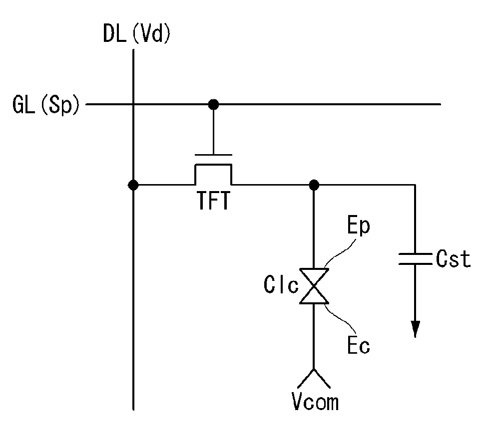
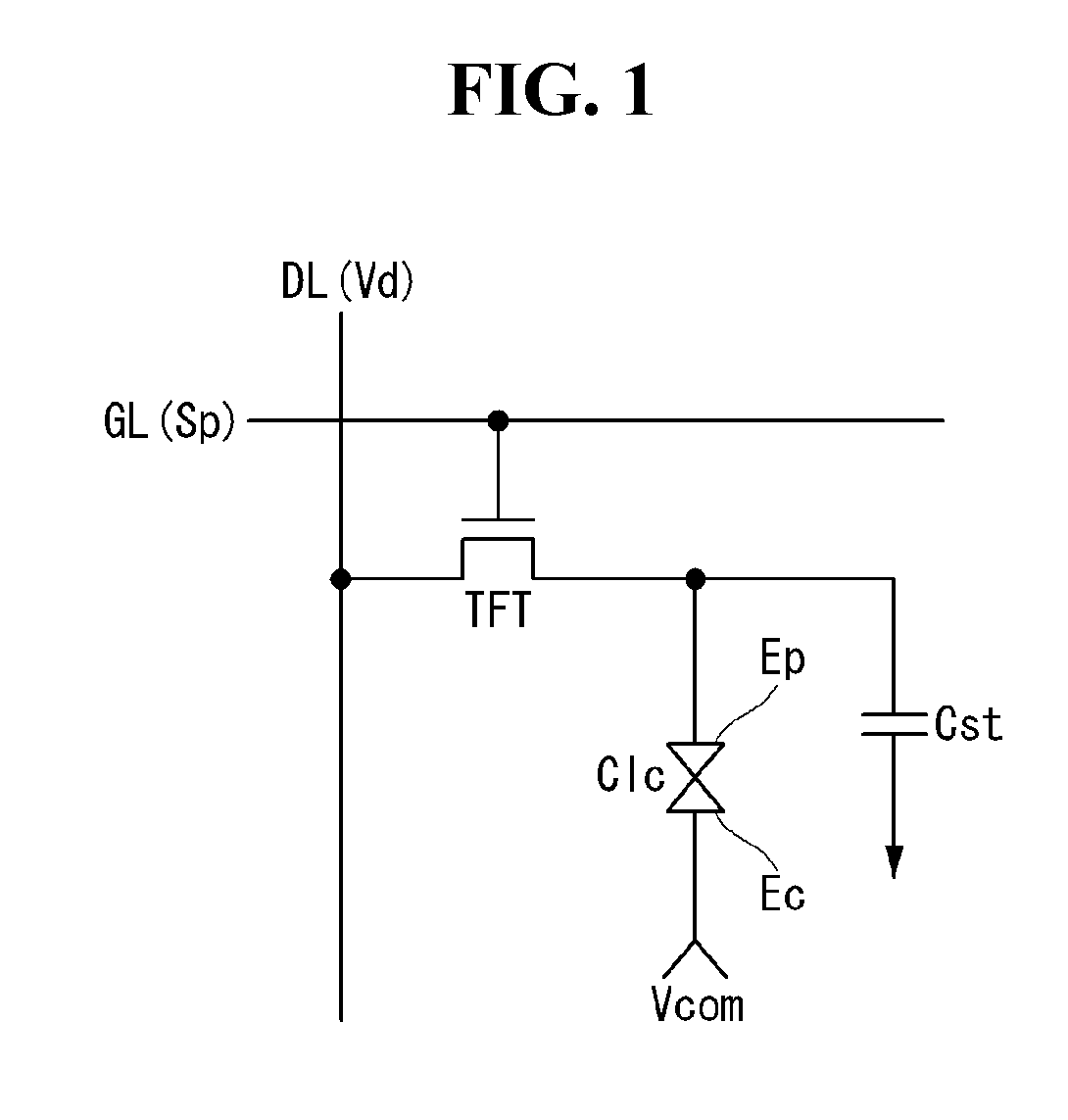
[0034]The liquid crystal display panel 100 comprises liquid crystal molecules disposed between two glass substrates. The liquid crystal display panel 100 comprises m×n (m and n are positive integers) liquid crystal cells Clc disposed in a matrix form based on a crossing structure of data lines D1 to Dm and gate lines G1 to Gn.

[0035]A lower glass substrate of the liquid crystal display panel 100 comprises a pixe...


PUM


Abstract

A liquid crystal display generates k DEMUX control signals for controlling the turn-on time of the DEMUX switches so as not to overlap with each other, and generates at least some of the DEMUX control signals every 2 horizontal periods, and makes 1 pulse sustaining period of the DEMUX control signals generated every 2 horizontal periods to overlap with a tail portion of the preceding horizontal period and a front portion of the subsequent horizontal period, among two neighboring horizontal periods.

Description

CROSS-REFERENCE TO RELATED APPLICATION[0001]This application claims priority to Republic of Korea Patent Application No. 10-2011-0128181 filed on Dec. 2, 2011, which is incorporated herein by reference in its entirety.BACKGROUND[0002]1. Field[0003]The present invention relates to a liquid crystal display, and more particularly, to a liquid crystal display which can reduce the number of output channels of a data driving circuit and a driving method thereof.[0004]2. Description of the Related Art[0005]A liquid crystal display displays an image by adjusting the light transmittance of liquid crystal using an electric field. Such a liquid crystal display comprises a liquid crystal display panel having liquid crystal cells arranged in a matrix form and driving circuits for driving the liquid crystal cells.[0006]On the liquid crystal display panel, as shown in FIG. 1, a gate line GL and a data line DL cross each other, and a thin film transistor (hereinafter, referred to as “TFT”) for driv...

Claims


Application Information

Patent Timeline
Patent Type & Authority Applications(United States)
IPC IPC(8): G09G3/36
CPCG09G3/3685G09G2310/0297G09G3/3688G09G2310/08G09G3/36
Inventor KIM, SANGHO
Owner LG DISPLAY CO LTD
Why Eureka
Try Eureka