Infrared Camera

a technology of infrared camera and infrared radiation, which is applied in the field of infrared camera, can solve the problems of poor image resolution, difficult to form good images, and inability to accurately detect the infrared radiation emitted by objects, and achieves high accuracy shading correction, good image, and reduced temperature fluctuation

Inactive Publication Date: 2013-06-06
TAMRON
View PDF2 Cites 12 Cited by
  • Summary
  • Abstract
  • Description
  • Claims
  • Application Information

AI Technical Summary

Benefits of technology

[0019]The infrared camera according to the present invention enables shading correction among the shutter and the infrared lens group because the shutter having a temperature sensor is arranged on the infrared light path in the housing from the window to the infrared lens group unit. Then, highly accurate shading correction based on the temperature of the shutter detected by the temperature sensor makes forming of good image possible.
[0020]Further, sealing inside of the housing can reduce temperature fluctuation in the housing because the inside of the housing is protected from the influence of heat from outside. Then, the reduced influence of temperature fluctuations during shading correction makes forming of good image possible.

Problems solved by technology

Such infrared radiation emitted from the objects such as components of the infrared camera will cause ill effects on imaging of infrared radiation emitted from the object.
However, the infrared camera disclosed in Patent Document 1 provided with the shutter in the imaging side of the infrared optical system has the following problems.
No shading correction in the infrared optical system locates in the object side of the shutter will result a poor image resolution and have been hard to form good images.
However, the correction using the software causes problems not only complex control system but also cost increase because of installation of different software when the infrared optical system is replaced.
Then, such maintenance will cause problem, readjustments of the optical system will be required because of failure of the optical system caused by improper optical balance.
Further, conventional shading correction using a shutter has been caused another problem that temperature fluctuation in the shutter affects the resolution of images, and it makes formation of good images difficult.
Especially when the shutter is arranged at a location close to the infrared image sensor, the shutter tends to be affected by heat generated in the infrared image sensor and cause inconvenience such as an attractive fixed pattern noise in images.

Method used


Image

  • Infrared Camera
  • Infrared Camera
  • Infrared Camera

Examples


first embodiment

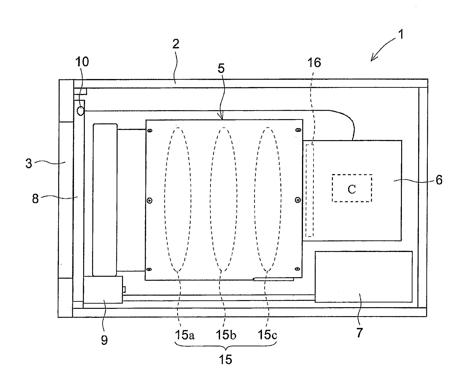
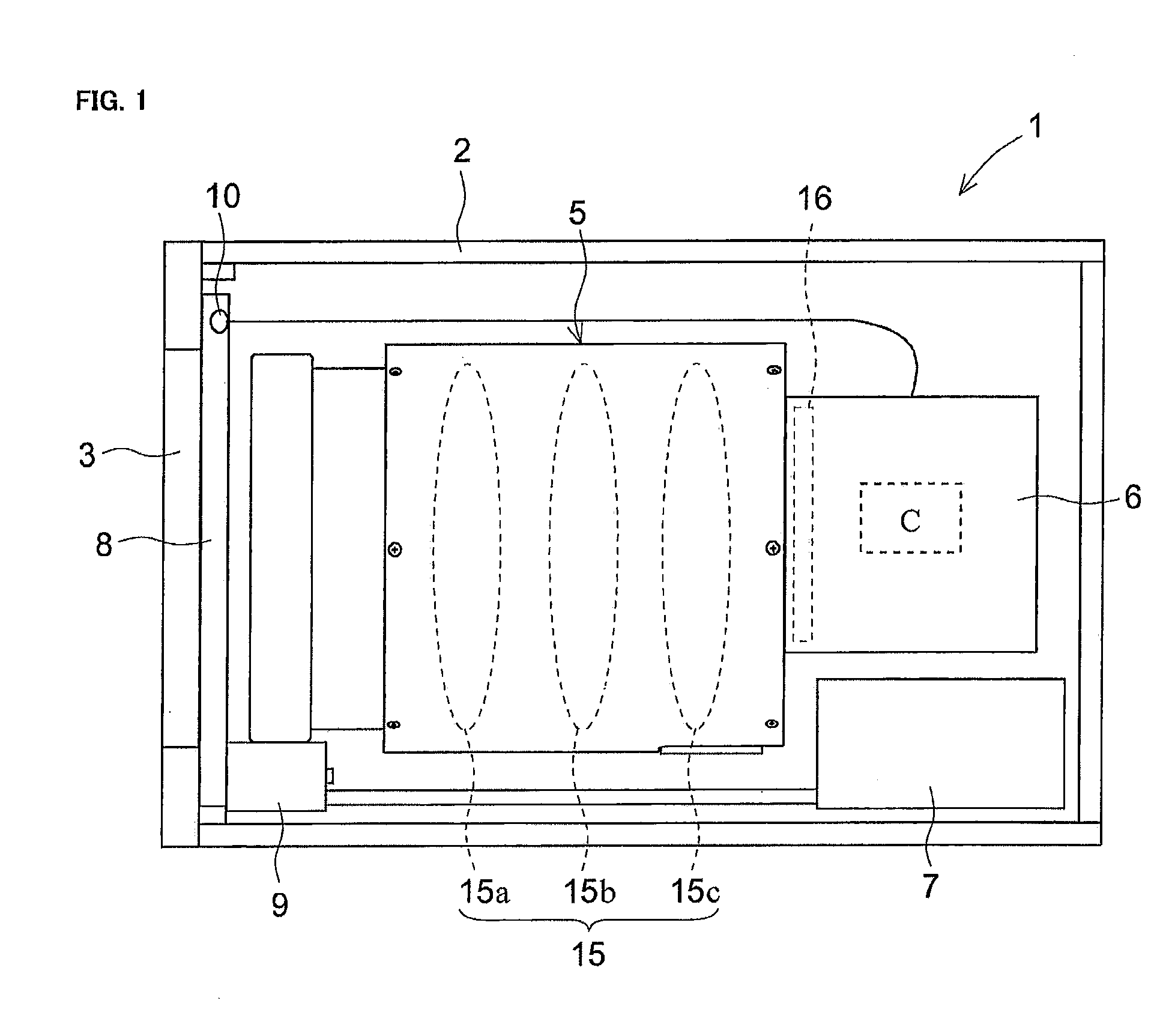
[0026]Structure of infrared camera: A structure of an infrared camera according to a first embodiment will be described first with reference to FIG. 1. FIG. 1 is a diagram schematically illustrating an internal structure of the infrared camera according to the first embodiment of the present invention. As shown in FIG. 1, in the infrared camera 1 according to the present invention, components such as an infrared lens unit 5, a camera body 6, a power supply circuit board (power supply) 7 are contained in a housing 2 of the infrared camera 1.

[0027]The housing 2 constitutes the outer case of the infrared camera 1. The housing 2 is substantially cylindrical. Further, the space in the housing 2 is sealed. Then, in the object side of the housing 2, the window 3 is formed at a portion facing to the object side of the infrared lens group 15 of the infrared lens unit 5.

[0028]The window 3 is made of an infrared-transparent material. As the infrared-transparent material, it is preferable to us...

second embodiment

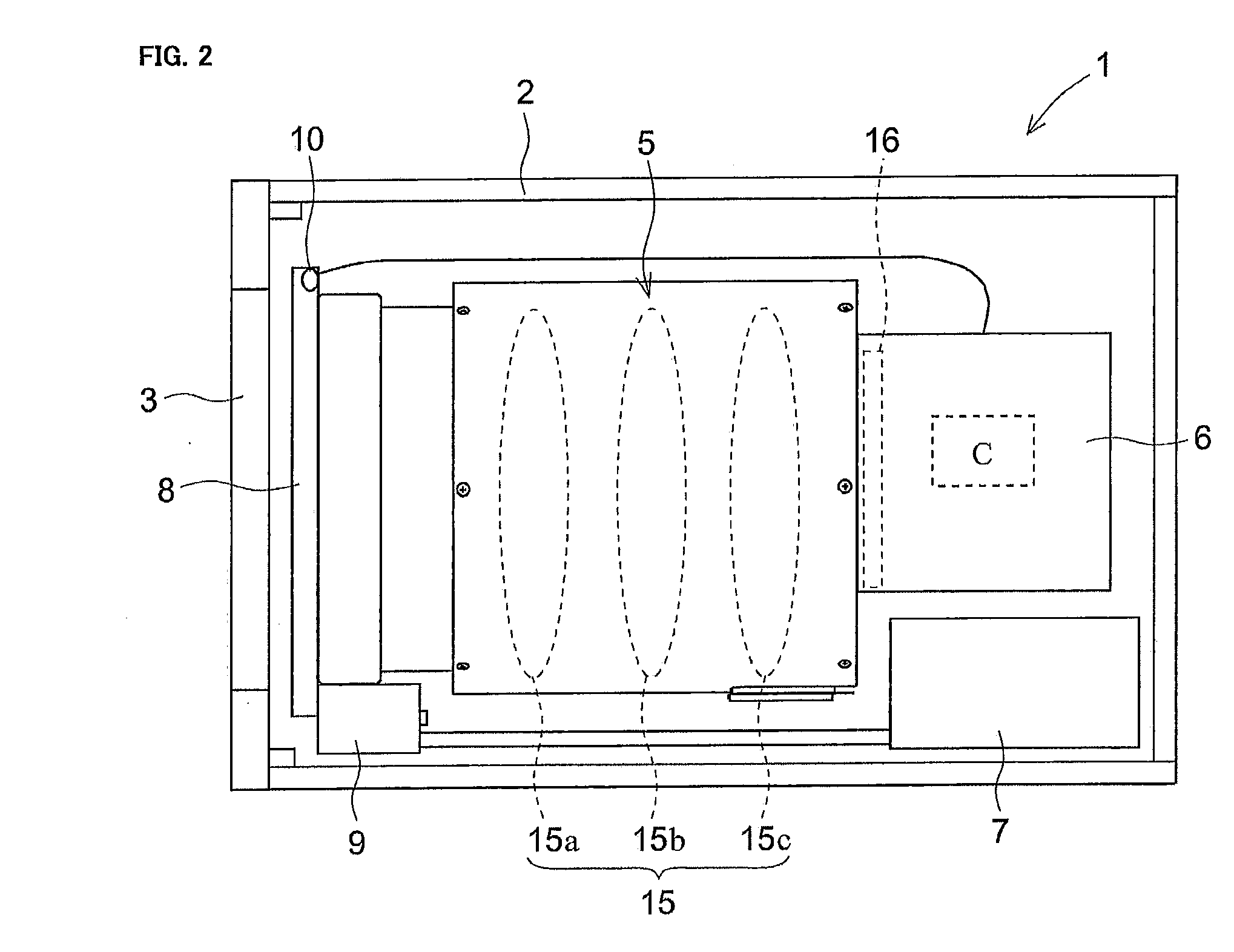
[0051]FIG. 2 schematically illustrates an infrared camera according to a second embodiment. The infrared camera 1 according to the second embodiment has a shutter 8 arranged closest to the object side of an infrared lens group 15. In the infrared camera 1 according to the present embodiment, the shutter 8 is arranged in a location in the object side of the infrared lens 15a and closest to the infrared lens 15a of the infrared lens group 15 as shown in FIG. 2.

[0052]Note that difference in FIG. 2 form the first embodiment is just the location of the shutter 8, and the structure and operation are the same with the first embodiment. Therefore, description of the same components and operation as those in the first embodiment will be omitted.

[0053]The shutter 8 shown in FIG. 2 may be attached on an infrared lens unit 5, instead of being attached to the inner wall of the housing 2 as in the infrared camera 1 of the first embodiment described above. Specifically, an attachment that extends ...

third embodiment

[0055]An infrared camera according to a third embodiment will be described next with reference to FIG. 3. The components labeled with signs the same as components of the infrared camera 1 of the first embodiment have effects or functions that are the same as or similar to those components and therefore description on those components will be omitted here.

[0056]Structure of infrared camera: A structure of the infrared camera of the third embodiment will be described first. As shown in FIG. 3, the infrared camera 100 according to the present invention includes components such as an infrared lens unit 5, a camera body 6, and a power supply circuit board 7, all of which are contained in a housing 2 of the infrared camera 100. Inside of the housing 2 which constitutes the outer case of the infrared camera 100 is a sealed space.

[0057]The camera body 6 includes a controller C that controls operations of the infrared camera 100. The controller C has the function of correcting a captured ima...


PUM


Abstract

An object of the present invention is to provide an infrared camera capable of shading correction with ease and an improved degree of accuracy and has good maintenance ability. To achieve the object, an infrared camera provided with an infrared lens group and an infrared image sensor located at an image focusing surface of the infrared lens group in a housing in which a window is formed at a portion facing the object side of the infrared lens group comprising: a controller correcting a captured image according to an output from the infrared image sensor and outputting the corrected image; a shutter arranged on an infrared light path in the housing from the window to the infrared lens group; and a temperature sensor detecting the temperature of the shutter is adopted.

Description

BACKGROUND OF THE INVENTION[0001]1. Field of the Invention[0002]The present invention relates to an infrared camera made proper shading correction enable.[0003]2. Description of the Related Art[0004]An infrared camera is a camera which captures the thermal image data of the object by using infrared lenses made of an infrared-transparent optical material and forming an image of infrared radiation emitted from an object on an image sensor arranged at the image focusing surface of the infrared lenses. In the recent years, a human sensing using such infrared cameras has been widely used in various fields such as security and automobile applications.[0005]However, infrared radiation emitted from other objects such as components of the infrared camera simultaneously enters into an optical system of an infrared camera in addition to infrared radiation emitted from an object. Such infrared radiation emitted from the objects such as components of the infrared camera will cause ill effects on...

Claims


Application Information

Patent Timeline
Patent Type & Authority Applications(United States)
IPC IPC(8): H04N5/33
CPCH04N5/33
Inventor MATSUMOTO, TAKEHIRO
Owner TAMRON
Why Eureka
Try Eureka