Apparatus and method for generating medical isotopes

a technology of isotopes and apparatuses, applied in the field of system for generating isotopes, can solve the problems of difficult to maintain a stable power level, increase power, and increase the risk of nuclear proliferation associated with such out-of-country shipments, so as to improve reaction stability, improve the effect of geometry and enhanced cooling

Active Publication Date: 2013-06-06
WISCONSIN ALUMNI RES FOUND +1
View PDF9 Cites 23 Cited by
  • Summary
  • Abstract
  • Description
  • Claims
  • Application Information

AI Technical Summary

Benefits of technology

The present invention provides a better design for a vessel used to create medical isotopes. The design is a thin annulus that holds a solution containing the material used for the isotop. By controlling the shape of the annulus, the reaction is made more stable and the cooling process is improved. This results in a more efficient and effective production of the desired isotop.

Problems solved by technology

The technical problem addressed in this patent is the unstable power level of aqueous reactors used for generating medical isotopes. This instability can result in potential safety impacts and requires a control system that can react quickly to maintain constant power. The patent proposes a solution to this problem by incorporating a stable power level into the system.

Method used


Image

  • Apparatus and method for generating medical isotopes
  • Apparatus and method for generating medical isotopes
  • Apparatus and method for generating medical isotopes

Examples


Embodiment Construction

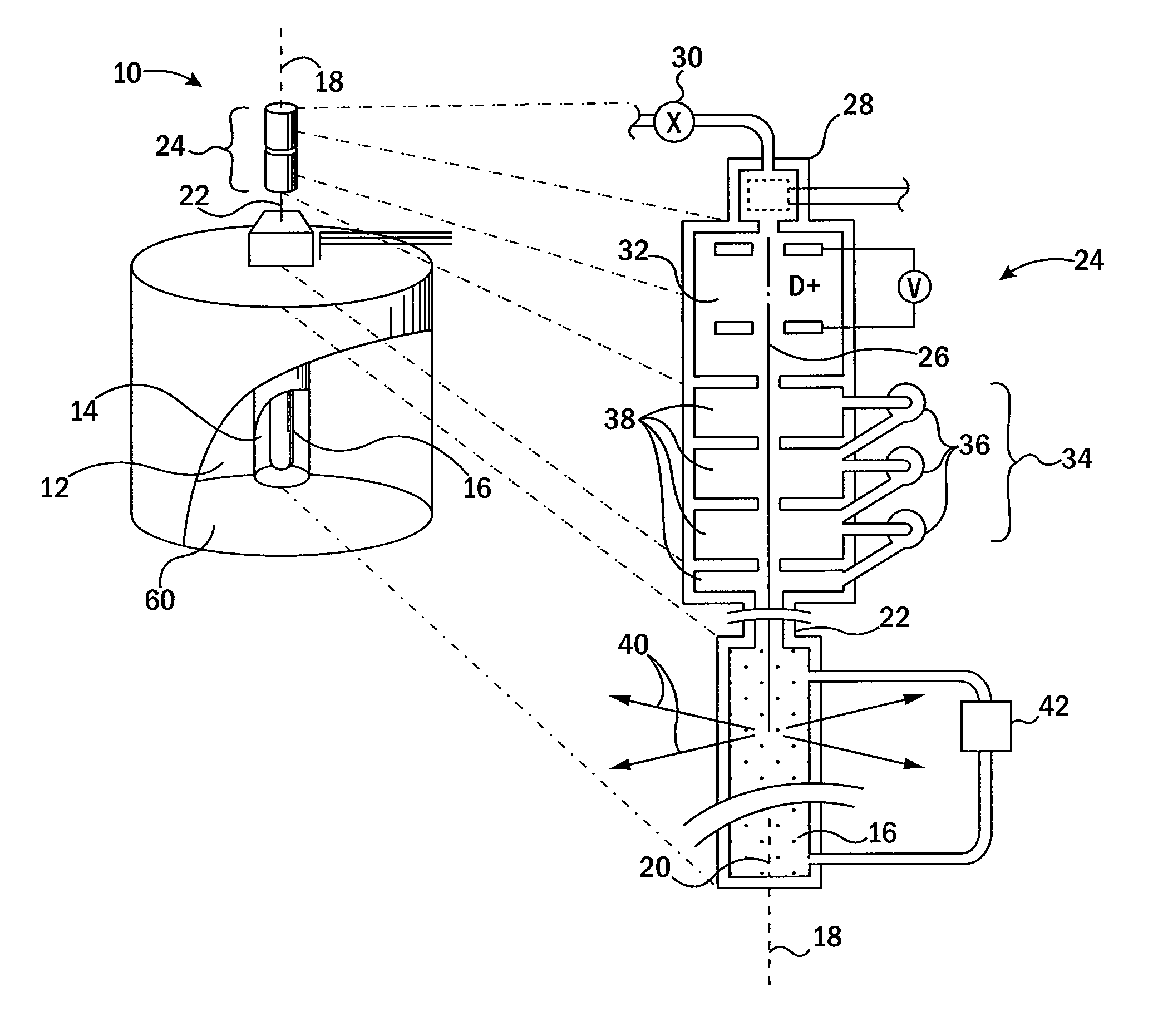
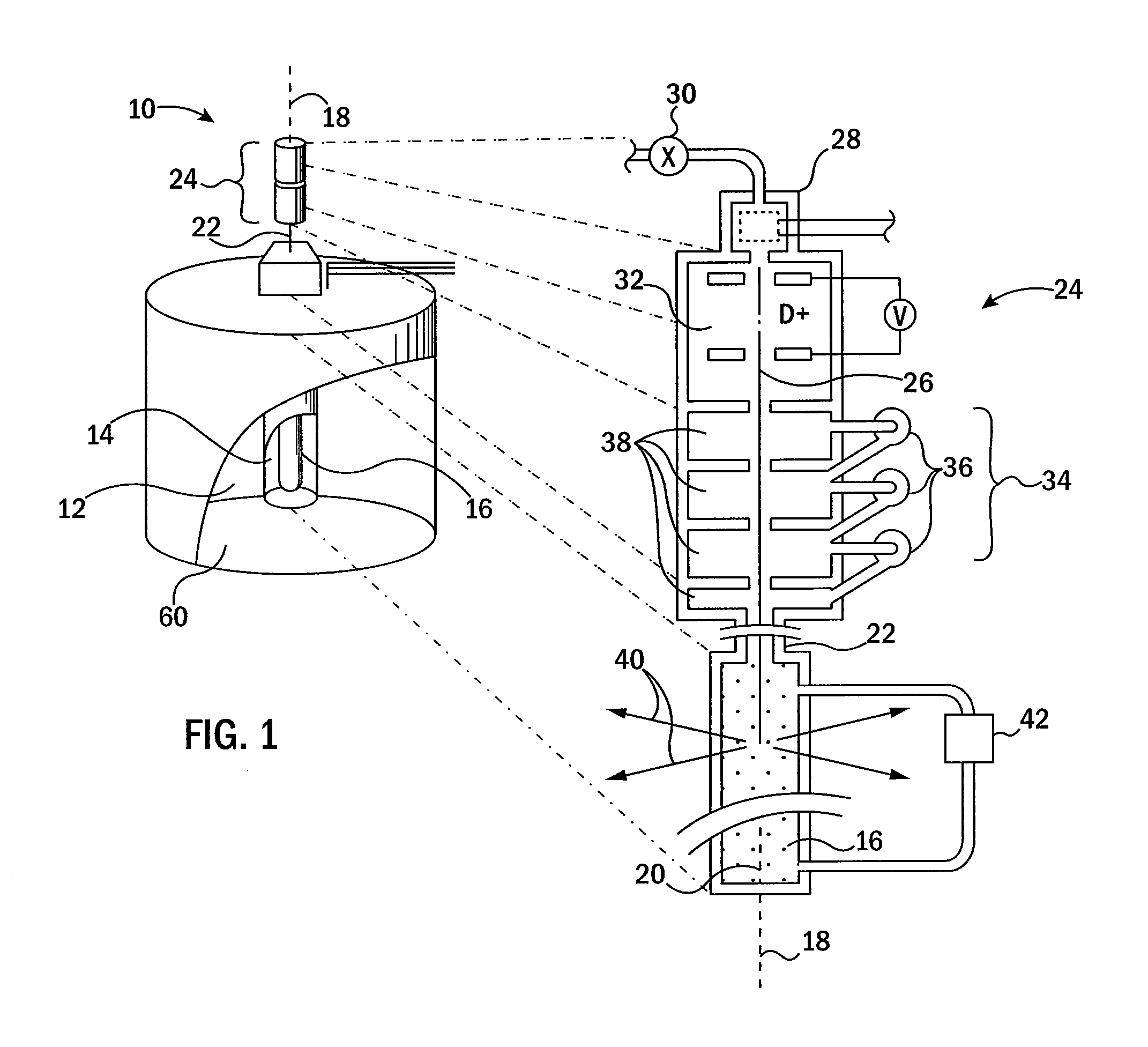
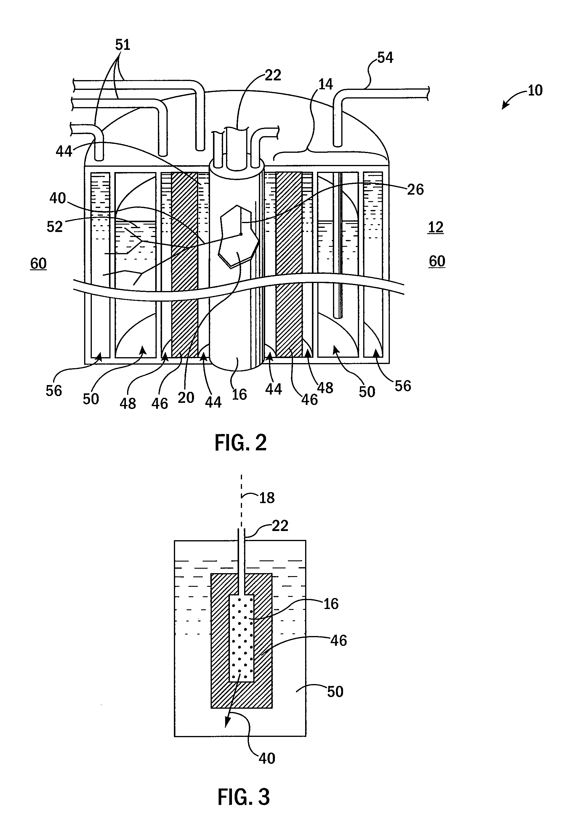
[0033]Referring now to FIG. 1, a medical isotope generator 10 of the present invention may provide a set of nested annular elements including an outer annular reflector chamber 12 surrounding and coaxial with an annular reactor assembly 14. A cylindrical target chamber 16 fits within the annular reactor assembly 14 so that all three elements of the annular reflector chamber 12, annular reactor assembly 14, and target chamber 16 share a common central axis 18.

[0034]The outer annular reflector chamber 12 may be taller than the annular reactor assembly 14 to provide a substantially equal thickness of reflecting material around the annular reactor assembly 14 in a direction perpendicular to central axis 18, and above and beneath the annular reactor assembly 14 in directions along central axis 18. In this embodiment, the annular reactor assembly 14 may be substantially equal in height to the target chamber 16.

[0035]The target chamber 16 may be a vertically oriented cylindrical shell exte...


PUM


Abstract

An apparatus for generating medical isotopes provides an annular fissile solution vessel surrounding a neutron generator. The annular fissile solution vessel provides for good capture of the emitted neutrons and a geometry that provides enhanced stability in an aqueous reactor. A neutron multiplier and/or a neutron moderator may be used to improve the efficiency and control the criticality of the reaction in the annular fissile solution vessel.

Description


Claims


Application Information

Patent Timeline
Owner WISCONSIN ALUMNI RES FOUND
Why Eureka
Try Eureka