
Transmission system for shift by wire

a transmission system and wire technology, applied in mechanical equipment, gearing control, transportation and packaging, etc., can solve the problems of frequent generation of malfunctions or breakdowns, and achieve the effect of improving operation speed and response, and minimizing malfunctions

Inactive Publication Date: 2013-06-13
HYUNDAI MOTOR CO LTD +1
View PDF21 Cites 3 Cited by
  • Summary
  • Abstract
  • Description
  • Claims
  • Application Information

AI Technical Summary

Benefits of technology

The present invention is about a transmission system for shift-by-wire that can prevent malfunctions and breakdowns of the solenoid. This is done by controlling the frequency at which the solenoid operates. The invention uses a PWM current signal to improve the speed and response of the solenoid during the initial shift-lock operation, and a duty rate that maintains the position of the solenoid during the maintenance operation after the initial operation. Overall, this results in a more reliable and efficient transmission system for shift-by-wire.

Problems solved by technology

However, in the transmission system for shift-by-wire of the related art, the solenoid keeps operating by a DC current from the initial operation to the maintenance operation for shift-lock, such that malfunction or a breakdown is frequently generated by operational high temperature / heating.

Method used


Image

  • Transmission system for shift by wire
  • Transmission system for shift by wire
  • Transmission system for shift by wire

Examples


Embodiment Construction

[0021]Reference will now be made in detail to various embodiments of the present invention(s), examples of which are illustrated in the accompanying drawings and described below. While the invention(s) will be described in conjunction with exemplary embodiments, it will be understood that present description is not intended to limit the invention(s) to those exemplary embodiments. On the contrary, the invention(s) is / are intended to cover not only the exemplary embodiments, but also various alternatives, modifications, equivalents and other embodiments, which may be included within the spirit and scope of the invention as defined by the appended claims.

[0022]Hereinafter, an automatic transmission system for shift-by-wire according to an exemplary embodiment of the present invention will be described in detail with reference the accompanying drawings.

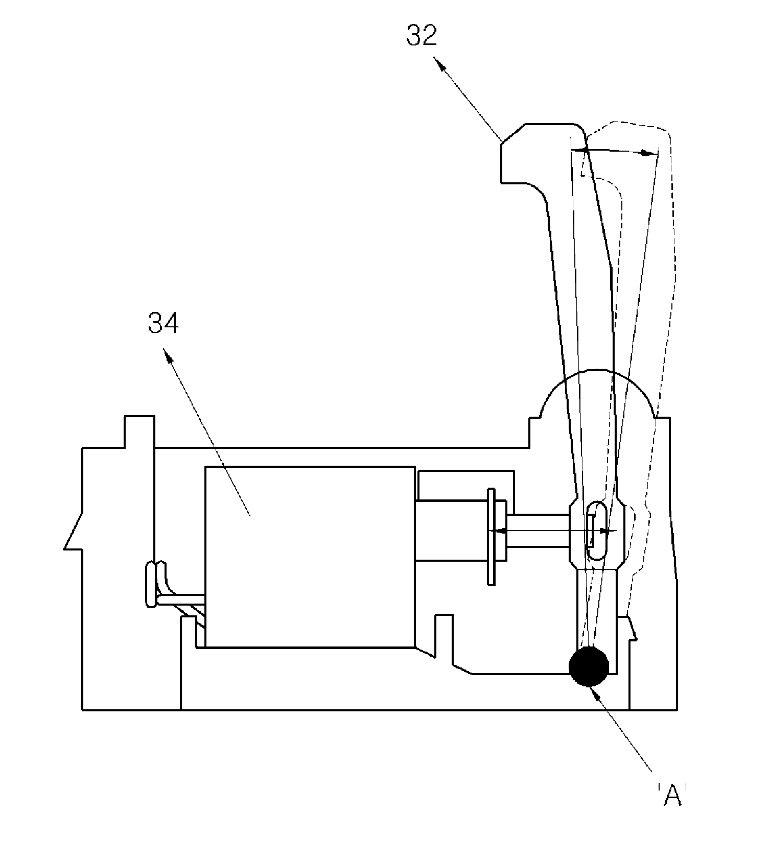
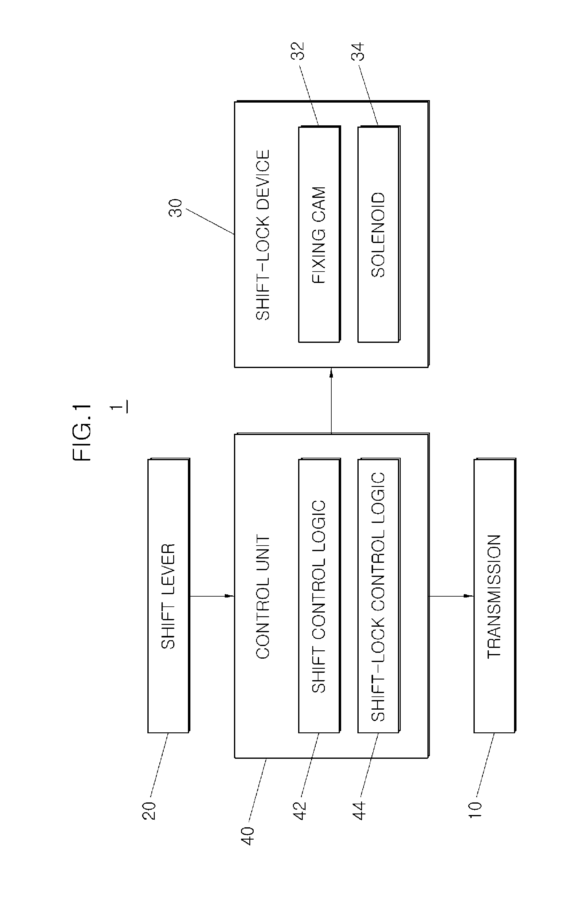
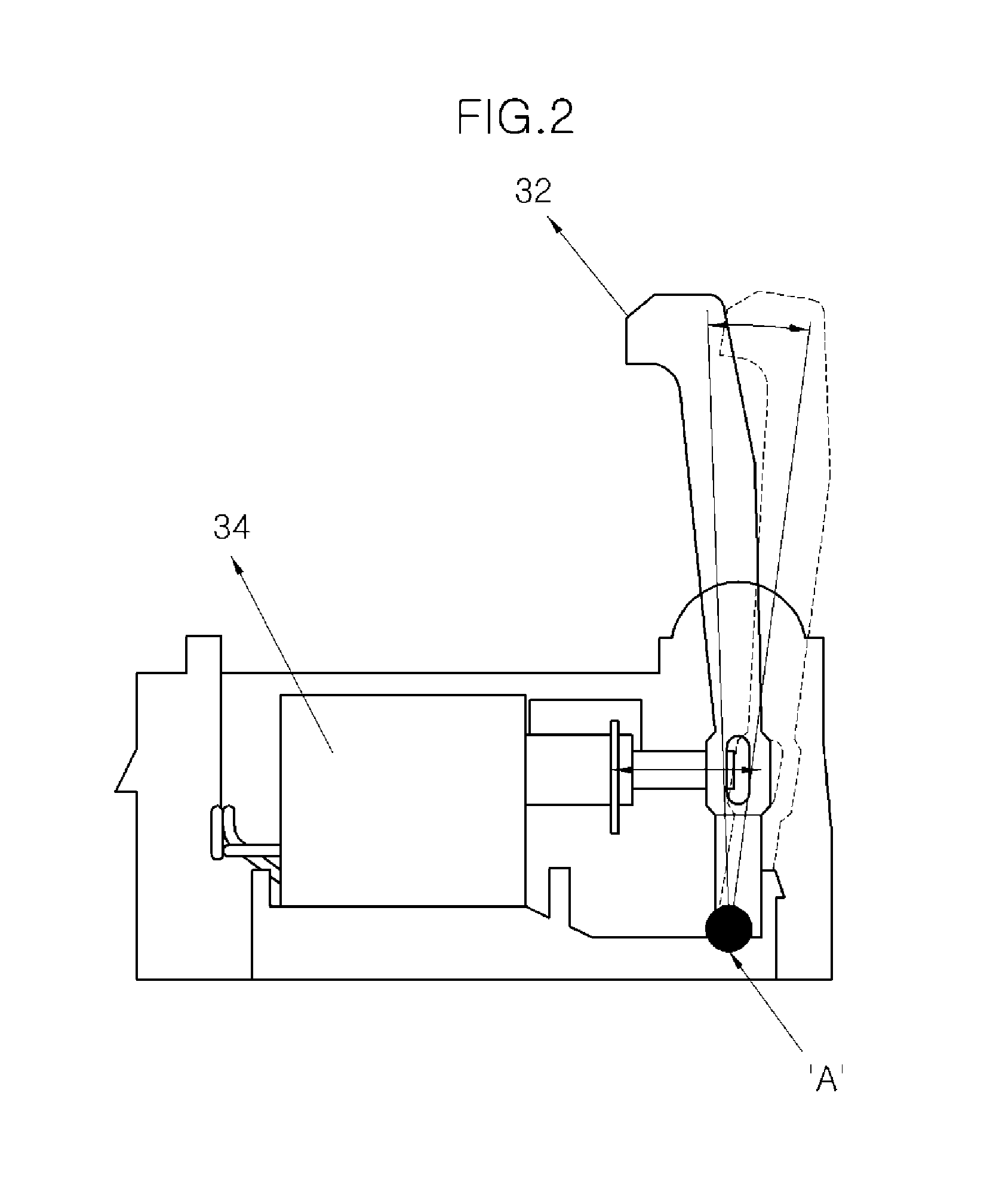
[0023]FIG. 1 is a block diagram of an automatic transmission system for shift-by-wire 1 according to an exemplary embodiment of the pre...


PUM


Abstract

The automatic transmission system includes a shift lever for changing stages by a user, a shift-lock device for fixing or releasing the shift lever, and a control unit including a shift control logic changing the stages of the transmission in accordance with the stage changed by the shift lever and a shift-lock control logic controlling the shift-lock device by stages for an initial time and a maintenance time after the initial time from when the stages may be changed such that the shift lever may be fixed, in order to shift-lock the shifted shift lever when the stages may be changed by the shift control logic.

Description

CROSS-REFERENCE TO RELATED APPLICATIONS[0001]The present application claims priority to Korean Patent Application Number 10-2011-131539 filed Dec. 9, 2011, the entire contents of which application is incorporated herein for all purposes by this reference.BACKGROUND OF THE INVENTION[0002]1. Field of the Invention[0003]The present invention relates to a transmission system for shift-by-wire (SBW), and particularly, to a transmission system for shift-by-wire in which shift-lock of a shift lever is implemented by a solenoid.[0004]2. Description of Related Art[0005]A transmission system for shift-by-wire is a transmission that electronically performs shifting control by using a shift lever and an ECU and equipped with a shift-lock device for preventing shifting due to a wrong operation.[0006]A shift-lock device of a transmission system for shift-by-wire of the related art is necessarily equipped with a solenoid to implement a physical shift-lock structure of a shift lever.[0007]However, ...

Claims


Application Information

Patent Timeline
Patent Type & Authority Applications(United States)
IPC IPC(8): F16H59/02
CPCF16H61/22F16H2061/223Y10T74/2011Y10T74/20104Y10T74/20098Y10T74/20085Y10T74/2003B60K20/02F16H59/10F16H61/02F16H61/18
Inventor LEE, SUNGILPARK, HANGILLEE, CHANGHYUN
Owner HYUNDAI MOTOR CO LTD
Learn More