Lighting control system

a control system and light control technology, applied in the direction of electric variable regulation, process and machine control, instruments, etc., can solve the problems of inconvenient replacement of bulbs, so as to improve efficiency and reduce costs. , the effect of less expensive replacemen

Active Publication Date: 2013-06-13
LUMEN CACHE
View PDF3 Cites 90 Cited by
  • Summary
  • Abstract
  • Description
  • Claims
  • Application Information

AI Technical Summary

Benefits of technology

[0020]Another advantage of the present invention lighting system relates to flexibility. For example, since driverless LED bulbs are less expensive than driver containing LED bulbs, one can replace bulbs more inexpensively. As new, higher efficiency luminary technologies are developed, they may be replaced without changing the driver components.
[0021]One additional feature of the present invention is that the Cat 5 wire can be used, that is both inexpensive to install, and is also capable of conveying not only power between the driver and the bulb or sensor, but information between the driver and the sensor product. This feature has an advantage of helping reduce the installation costs of the lighting wire, and also enabling the lighting wire to carry not only current, but also signal information between the driver and a sensor product or other component within the house.
[0022]These and other features and advantages of the present invention will become apparent to those skilled in the art upon a review of the drawings and detailed description presented below, that represent the best mode of practicing the invention perceived presently by the Applicant.

Problems solved by technology

Incandescent light bulbs also have a drawback as they burn hot, and are inefficient in their use of power when compared to florescent lights.
Because of the inherent inefficiency, incandescent light bulbs are falling into disfavor.
Florescent lights raise health and / or environmental concerns, since florescent lights typically include mercury that is highly poisonous and creates an environmental hazard.
Another difficulty is that the light given off by most florescent lights is a very “cool” (blush) light that, while doing a fine job to illuminate a space, does not contain the warmer tones of an incandescent light bulb.
Further, unlike incandescent lights, florescent lights are not well adapted to provide a variable light output, such as can be accomplished through a dimmer without additional circuitry that has a significant impact on the cost of the bulb.
LED light bulbs are gaining favor because they are capable of providing a large amount of light and typically have a rather long life span.
One difficulty with the use of such driver-containing LED bulbs is that they can be expensive to replace.
However, since the bulb and the driver are combined in one inseparable unit, the useful life of the component with the shortest useful life typically governs the lifetime of the combined device, since, for example, when the driver burns out, the driver and bulb ust be replaced as a unit.
An additional issue relates to flexibility of the unit, since the driver and the bulb are combined.

Method used


Image

  • Lighting control system
  • Lighting control system
  • Lighting control system

Examples


Embodiment Construction

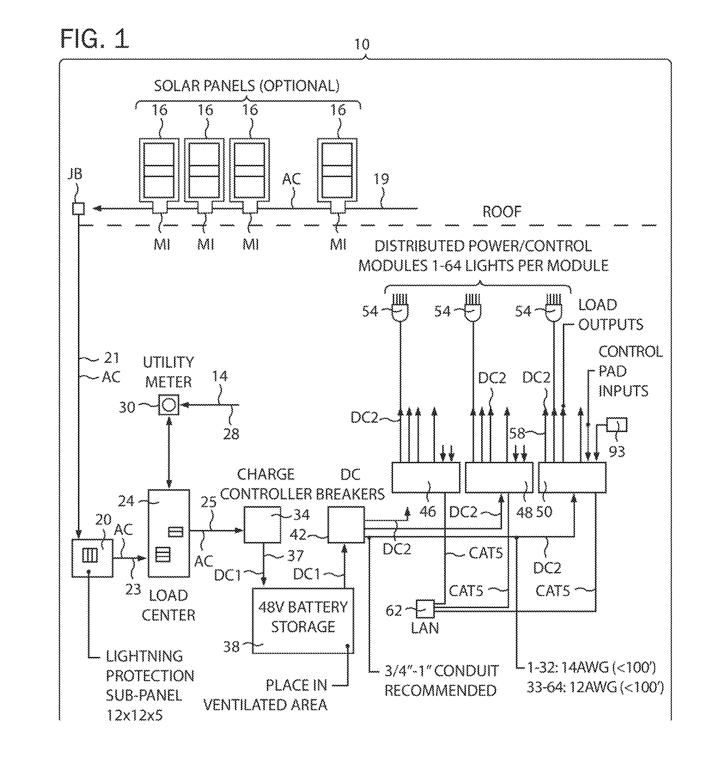
[0047]In the present invention, a lighting system comprises a bulb member that is powered by direct current (DC). The DC driven bulb is preferably an LED type bulb.

[0048]The driver is located remotely from the bulb, and preferably at a centralized or regionalized driver center. By centralized, one envisions a central bank of drivers that control all of the various lighting systems within a particular building or space. By regionalized, one is referring to a set of driver groups or gangs that would control a set of lights and the like. For example, there may be a regional driver gang that controls all of the lighting within the kitchen or first floor of the house, and a second regional gang that controls all of the lighting fixtures within one of the bedrooms.

[0049]A control mechanism is provided that controls the power delivered to both the drivers and the bulbs, and additionally performs communication functions so that communication can occur between the drivers, the bulbs, and / or ...


PUM


Abstract

A control system controls the operation of at least a first and a second independently controllable LED light member. The control system includes a frame member on which a plurality of electrical components can be mounted, and at least one input port for receiving at least one of a power source and a command signal source capable of sending a command signal to at least one of the first and second LED light members. A first driver member is provided for conducting power to deliver conditioned DC power to the first LED member. A first driver to frame connector removably couples the first driver member to the frame member. A second driver member conditions power to deliver conditioned DC power to the second LED member, and a second driver to frame connector removably couples the first driver member to the frame member. A first external output port is coupled to the first driver, and a second external output port coupled to the second driver. A first multi-channel electrical conductor is coupled to the first external output port for conducting conditioned DC current to the first LED light member; and a second multi-channel electrical conductor conducts conditioned DC current to the second LED light member.

Description

PRIORITY CLAIMS[0001]This Provisional application is related to, and claims benefit to Derek Cowburn, U.S. Provisional Patent Application Ser. No. 61 / 569,324 that was filed on 12 Dec. 2011 and Derek Cowburn, U.S. Provisional Patent Application Ser. No. 61 / 671 / 779 that was filed on 15 Jul. 2012, both of which are fully incorporated by reference herein.I. TECHNICAL FIELD OF THE INVENTION[0002]The present invention relates to lighting control systems, and more particularly, to a lighting control system that is especially adaptable for use with DC current driven lighting systems, such as LED lights.II. BACKGROUND OF THE INVENTION[0003]There are several types of building lighting systems in widespread use. Incandescent lighting systems are widely used currently. In an incandescent light AC current is passed through a filament housed in a vacuum bulb. The filament glows and gives off light.[0004]Incandescent light bulbs also have a drawback as they burn hot, and are inefficient in their u...

Claims


Application Information

Patent Timeline
Patent Type & Authority Applications(United States)
IPC IPC(8): H05B37/02H05B44/00
CPCH05B37/0254H05B37/02H05B47/18H05B47/10
Inventor COWBURN, DEREK
Owner LUMEN CACHE
Why Eureka
Try Eureka